I decided to put my 3D printer to work making a new backplate for a broken stove guard. Of course my 3D-fixing evolved into a tedious weekend project.
Repairing things gives me a good feeling. Especially so if it involves nerdy stuff like 3D modeling and printing. Creating more or less exact copies of broken parts, hereby called 3D-fixing, poses a significant challenge to 3D novices like me.
Then again, repairs like this tend to be even more rewarding, at least in terms of learning-by-doing.
Previously, I have done 3D modeling of electronic components while designing things like my broadcast clock or the dual button doorbell. These models are only ment for visual reference when planning PCB layout and so on. With 3d-fixing, it’s time to design something that will actually end up as a tangible, real-world object. You can download the final model from my profile on GrabCAD.
Tracing the outline
I started out attempting to measure and draw the footprint of the backplate in 2D software. That didn’t work out. I’m not much of a technical drafter, so I threw in the towel after a couple of hours.
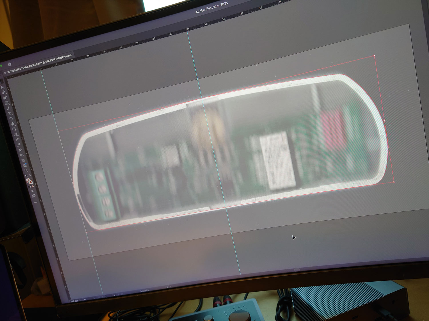
I went on to plan B, utilizing my scanner to produce an accurate raster image of the profile for the stove guard repair.
The image was imported at 1:1 ratio to Adobe Illustrator. I specified millimeters as grid unit, locked the image layer, dimmed it to 50% and started tracing the enclosure’s outer profile.
Working out the details
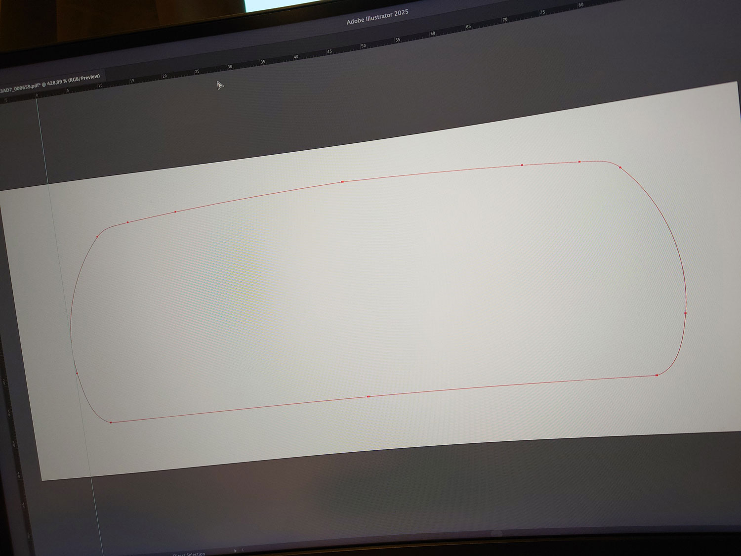
After tracing the profile, I ran Illustrator’s path>smooth tool on the result. I then split the shape on the exact center, discarded one side, replacing it with a mirrored version of the other side. This left me with a perfectly symmetric shape, well suited for 3D works.
Illustrator allows for direct export of a DXF version of the shape. I did have to open the exported file in QCAD to tidy up some of the points and get rid of a couple of other mishaps.
The final DXF file is available for download from GrabCAD, as well as the 3D model itself.
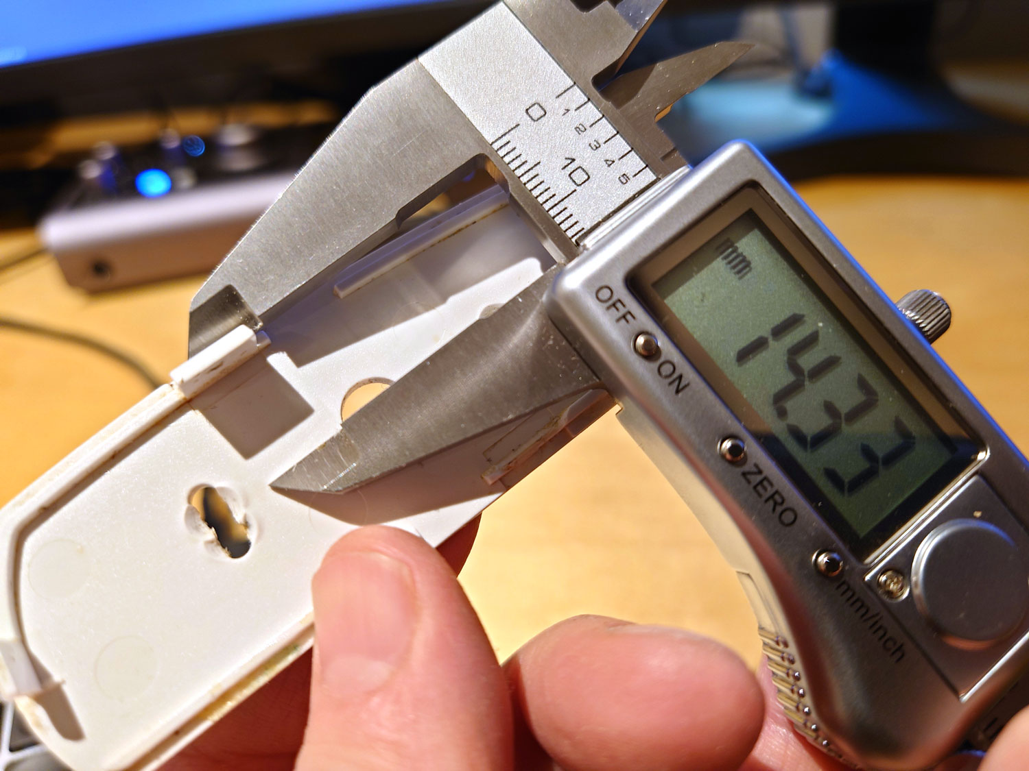
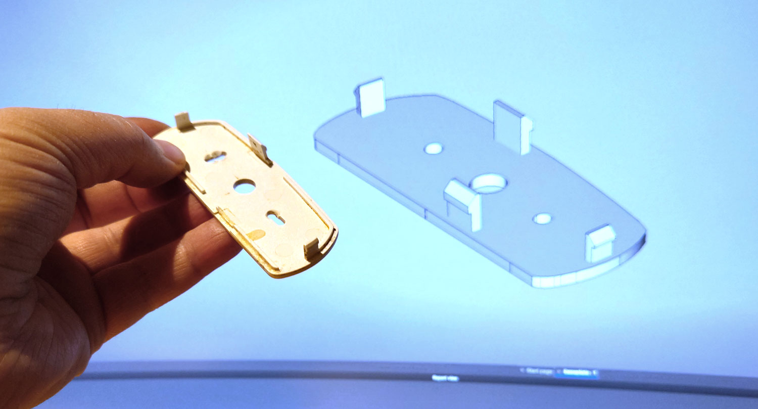
After importing the shape, I spent some time measuring out the repair. The snap-fit connectors had to be positioned accurately to match the notches on the counterpart. A caliper comes in very handy.
I use the open source tool FreeCAD to make my 3D models. It is a so-called parametric modeler, which means that you’ll have to draw out your models in terms of exact measurements (parameters) and constraints. Wikipedia has more on this.
Printing and mounting the repair
FreeCAD is very suited for technical drawing, hence it differs greatly from other common 3D applications like Blender. The learning curve is a bit steep, but in my opinion it’s really worth the effort.
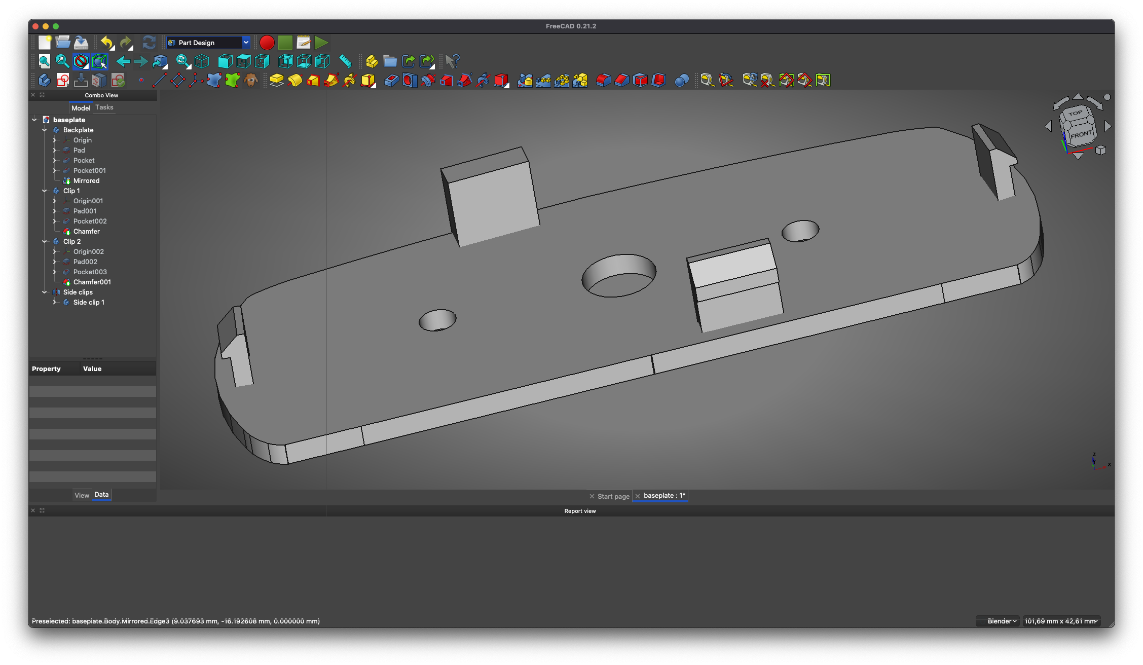
FreeCAD can export models to a variety of file formats including STL, which can be consumed by most 3D printing software.
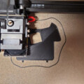
My choice of PETG filament might not be the best. I’ll go for something more rigid the next time I do such repair, even thought the result was quite usable indeed.
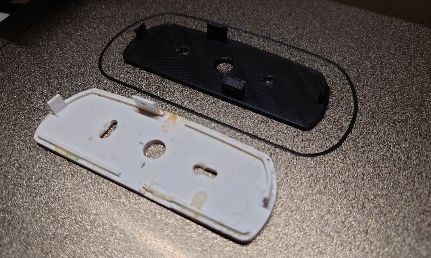
The new backplate snapped well in place, no worries. Should be ready for wall mount.
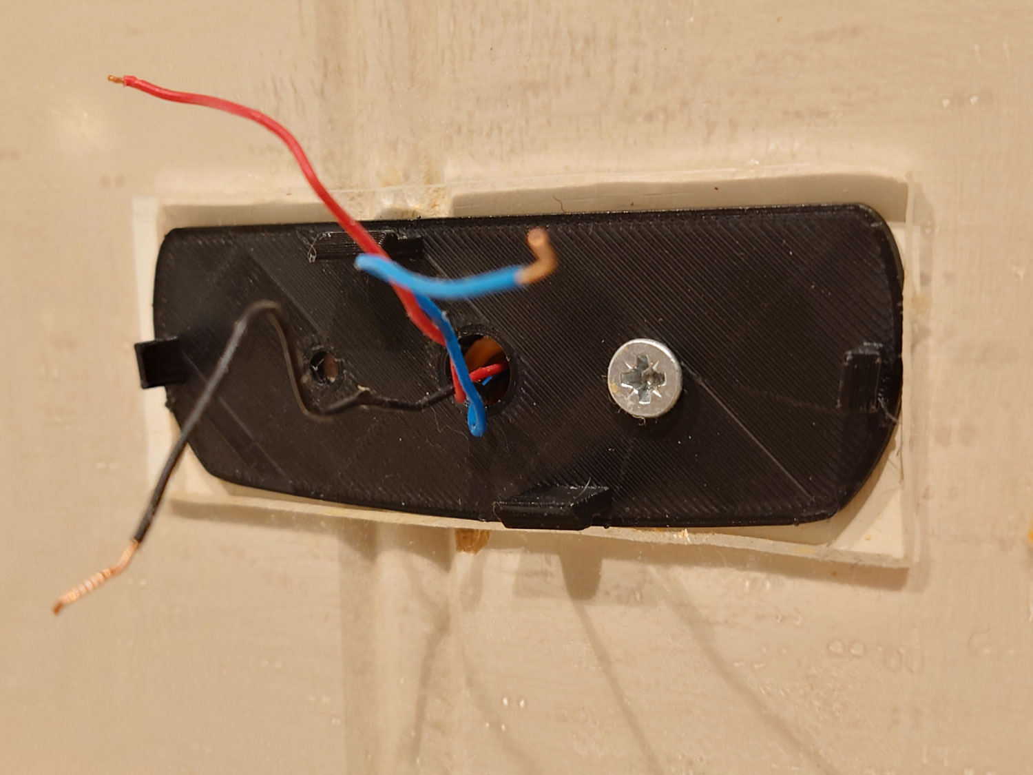
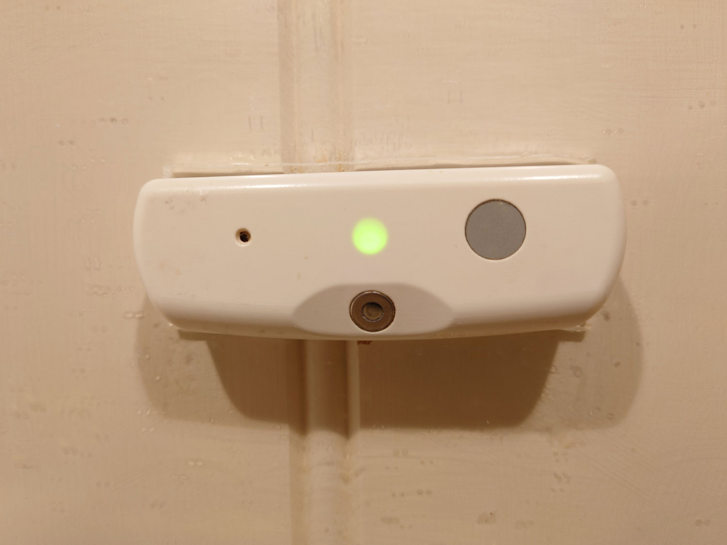
My stove guard is 3d-fixed for now! If you want a closer look on the model, including the DXF footprint, you’ll find it on GrabCAD.

Dette var en utrolig bra guide! Har ikke prøvd scanner-metoden før. Takk for tipset!
Hyggelig å høre! Lykke til, jeg bruker scanneren ofte, selv til enkle geometrier.