As I get older, concerns revolve around how to maintain a self-proclaimed status as the unequivocal nerdiest geek in town. So, here’s my ESP32 based, ultimate invitation card…
When you’re about to turn 50, certain concerns start to surface about whether you’re actually keeping up appearance.
Let’s just say I felt an urge to, uhm… replenish my hard earned image. Several years with kids almost made me appear as a normal family dude.
So, I decided to throw a nerd-themed birthday party, calling for a proper invitation card. And here we go…
WiFi module, OLED, bells and whistles
In fact, the project started out quite modest: How about making the invitation cards on printed circuit boards? Using the silk screen layer for the invitation text? Yeah!
As it turned out, creating a PCB with no higher purpose than being a written post card just felt wasteful. It had to be at least some components in place, right? Like a blinking LED or something…
Then came the idea of actually outputting the invitation card text on an OLED display, which in turn required a microcontroller. And, while we’re at it, it wouldn’t hurt adding a couple of menu buttons for navigation either.
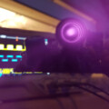
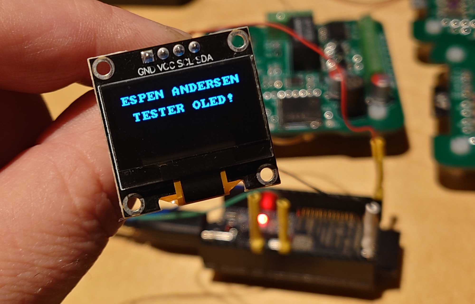
Controlling an output device over the I2C bus is very straight forward. Here’s a simple test run I did with a cheap 128×64 pixel 0.96″ OLED display.
I had a number of ESP32 WROVER B modules lying around from a previous project. I figured they would make great controllers for my invitation card.
Actually, they’re far too good not to be properly utilised. Using a hyper capable dual-core 240 MHz system-on-chip with 16 MB internal memory and wifi to merely drive a single 128×64 pixel OLED over i2c is like shooting sparrows with nuclear missiles!
So I went all in!
Invitation card circuitry
I thought I’d see what could be done with this module. So I set out to exploit its possibilities more thoroughly.
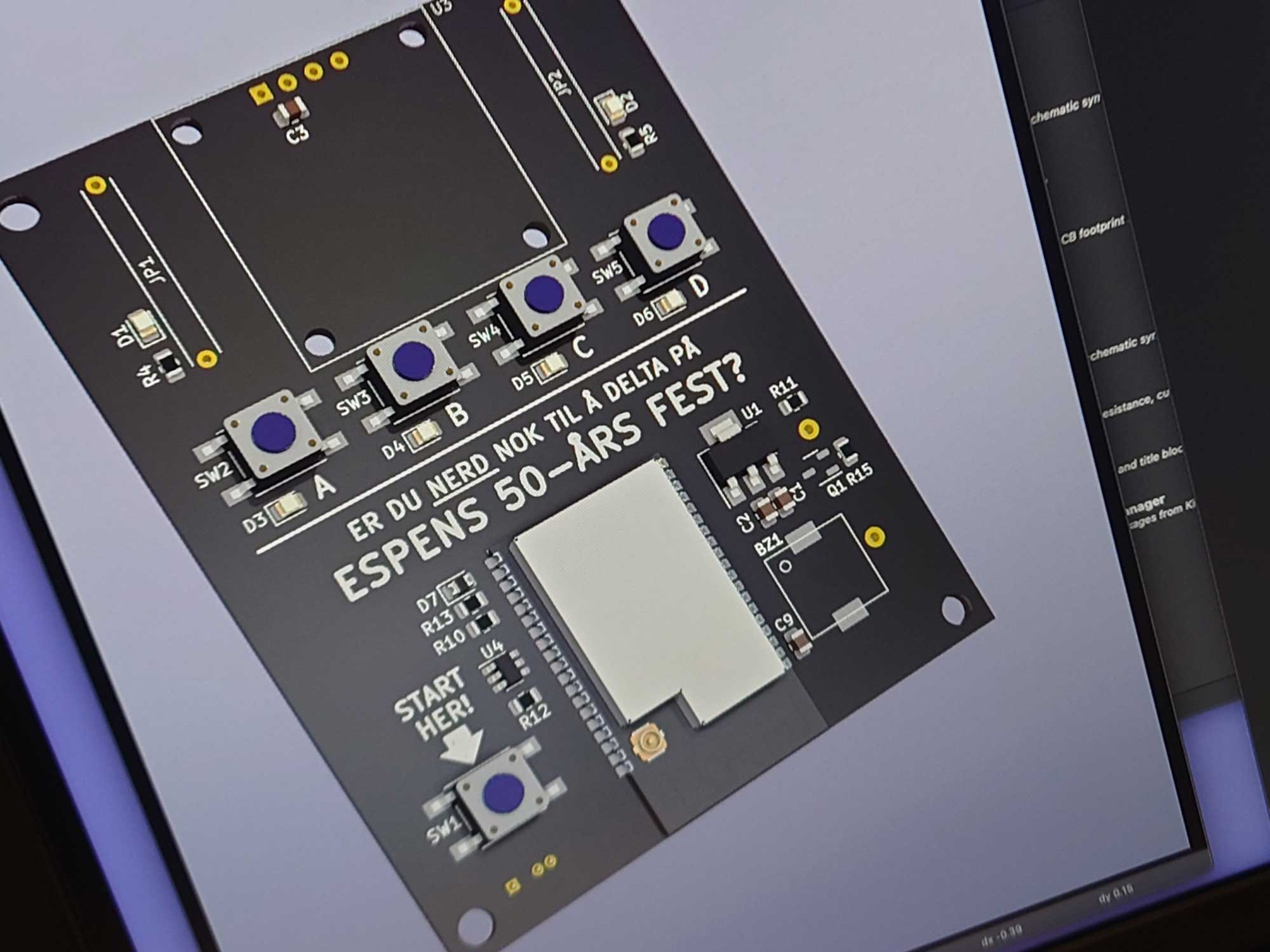
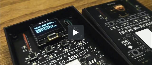
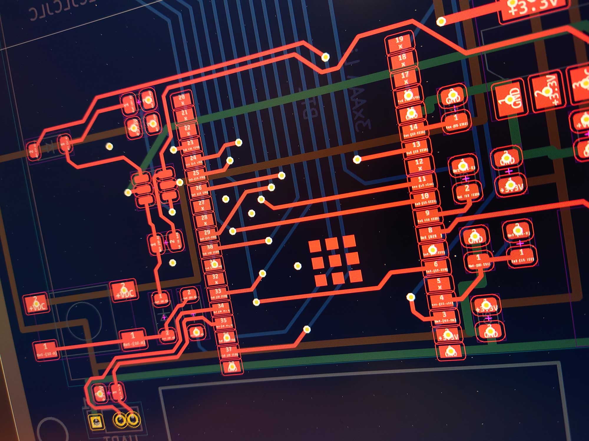
Initial attempt at designing the PCB invitation card. The Norwegian text at the center of the board reads “are you nerdy enough to attend Espen’s 50th birthday party?”
Here’s the feature list I ended up with for my invitation card — after a bit of brain storming:
- OLED display
- Animated graphics, scrolling text and menu system
- Menu selection buttons with LED indicators
- Two cuttable wires with LED indicators
- Piezo-transducer for sounding beeps and bloops
- Auto power off-timer
- Captive portal for internet connection provisioning
- DNS server to hijack client requests
- HTTP server providing a nice and nerdy captive portal
- Serial port for console logging and programming
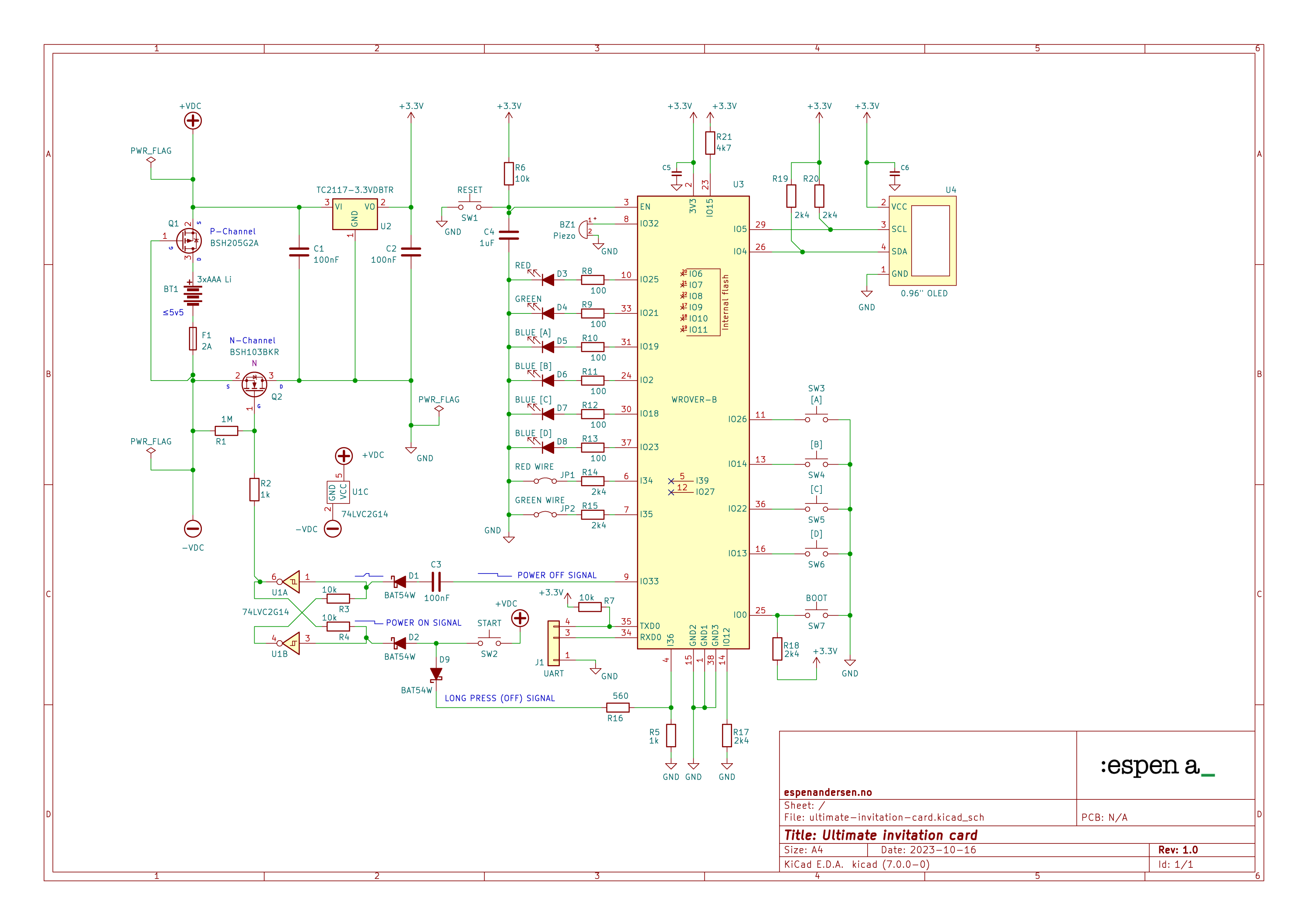
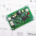
This is the circuit I eventually ended up with. Since it must be driven with lithium AAA cells, it includes a fuse (F1) reverse polarity protection (Q1) and some power management logic (Q2, U1).
I also included to jumper wires, one red (JP1) and one green (JP2), flanking the OLED module (U4). It’s much more fun letting the recipient fumble for a pair of pliers to cut the right wire during a somewhat tense 10-second countdown…
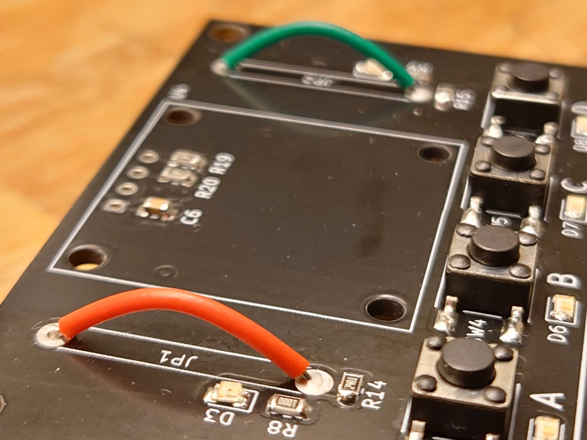
No pressure. It won’t explode on you. But the green wire is the one to cut if you plan on attending the party.
What will happen if the red wire gets cut is entirely for the recipient to find out. One of two animations will go off, depending on the user’s response.
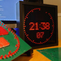
ESP32 test rig
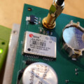
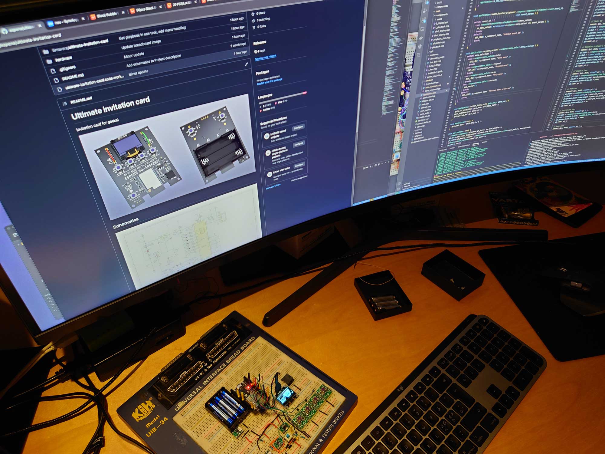
After drawing the schematics for the invitation card, I built a test version on a breadboard. The ESP32 ran with a minimum working firmware version.
I always make an effort in wiring up the breadboard version. I connect everything exactly as shown in the schematic. That gives me an excellent starting point for testing and debugging.
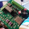
If I need to use SMD parts, dedicated breadboard adapters come in handy. For the WROVER module, I used a small development board that provides pin header sockets for most of its pins.
Text animations
I now had the means to start programming the ESP32. So I implemented some basic functionality to see if the MCU pin configuration worked as intended.
One interesting challenge was the interface to the OLED display. The invitation card required animated text, images and short videos to work. It took a fair amount of experimenting before finding a workflow. At the end of the day, I actually ended up creating text effects in Keynote.
I exported the keynote animation as a QuickTime movie,and opened it in Adobe After Effects. There, I scaled the video down to the OLED display’s resolution, which is 128×64 pixels.
From After Effects, I exported the animation as single frames, to make it easy to process the sequence in Photoshop. I created a batch job that converted the frames from grayscale to dot matrix (1 bit per pixel) bitmaps. This way the images could be rendered directly on the OLED display.
The online application image2cpp is a very convenient tool for converting graphics files to C++ byte arrays. The generated source code could be included directly in my project.
DNS hack
Implementing WiFi provisioning on the ESP32 was another challenge I had to take on. I wanted the invitation card to publish a WiFi network for a local connection. This way the client could provide credentials for a working internet connection.
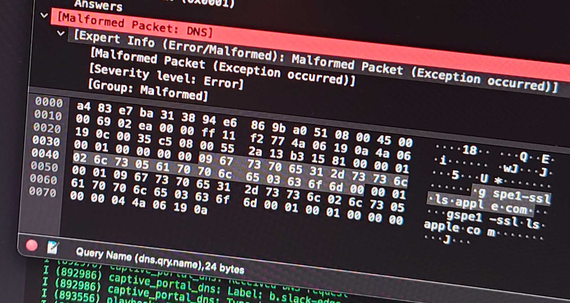
However, to get that to work, i had to implement a DNS server that directed every request to a so-called captive portal. In other words: I created a web page with input fields, served by the ESP32 itself. It took some deep packet inspection of DNS traffic with Wireshark to work that one out.
Nailing the invitation card size
In any case, I had to decide on the PCB dimensions, which in turn depended on the type of cardboard box I could find. It had to be relatively small, but still deep enough to accommodate the height of the finished board.
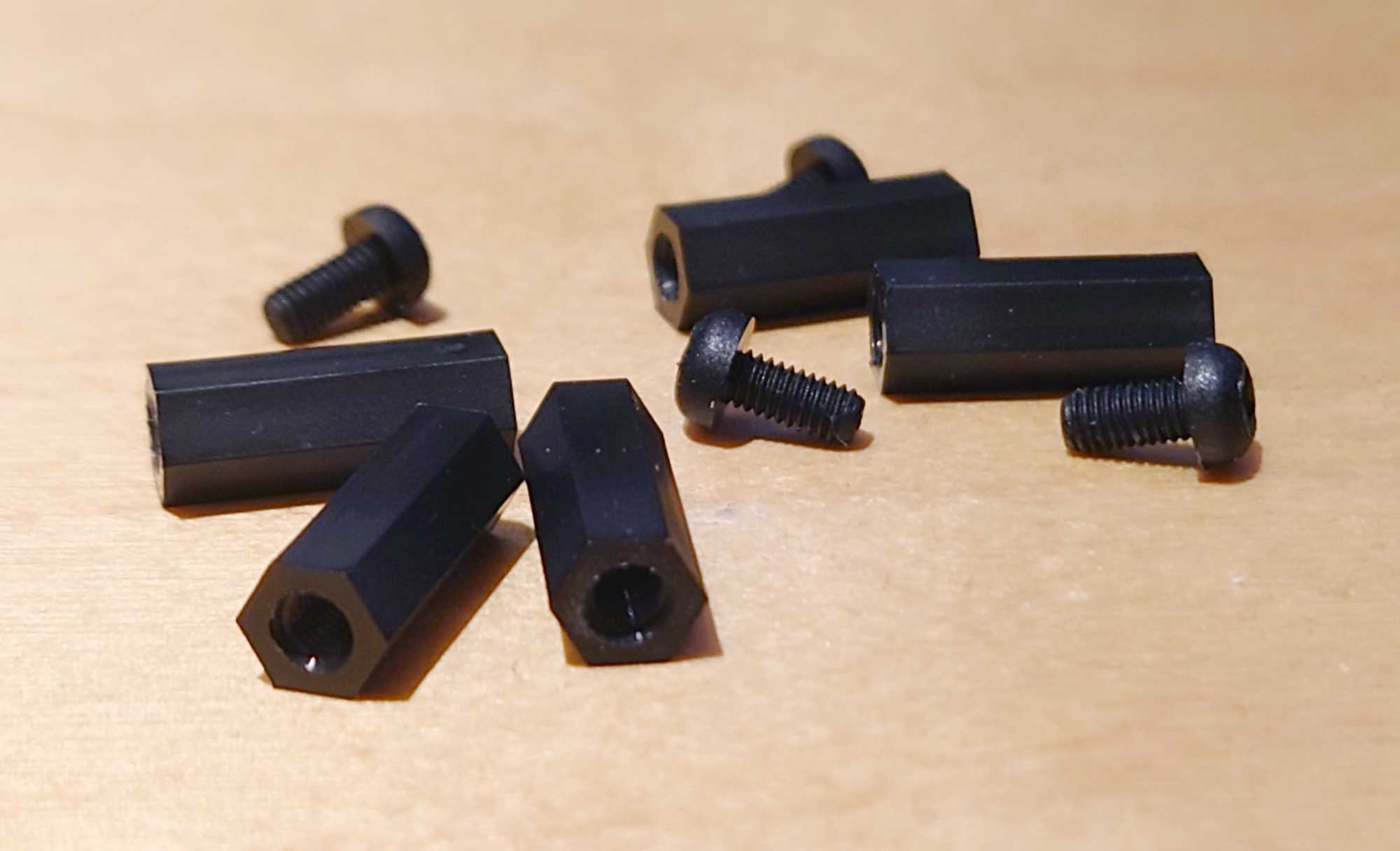
At the same time, I got hold of two types of nylon standoffs. One for keeping the board at a fixed distance from the bottom. Another to fix the display module a few millimeters above the PCB.
Nylon standoffs are very useful when mounting printed circuit boards. Their height matches the battery holder on the reverse side of the PCB, plus a few extra millimeters.
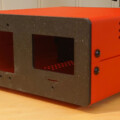
Knowing the exact height of the of the unit, I could start looking for a right-sized box.
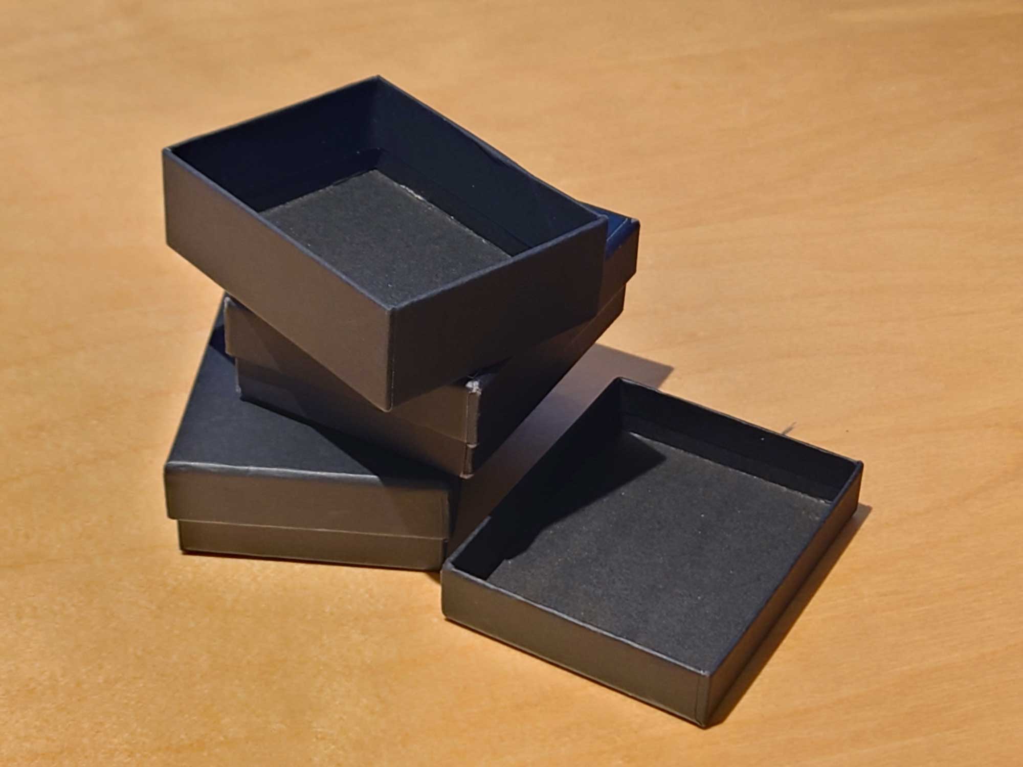
After browsing various online stores, I ordered a bunch of black, lidded boxes. They were originally intended for jewelries, but they still seemed perfect for my purpose.
I started drawing the invitation card edges in QCAD. The completed DXF outline was then imported to KiCAD for part placement and routing.
Invitation PCB design
The silk screen text calls the recipient to action. Hence it should be big, bold and prominently positioned on the front side.
I had to be wary not to place any components over the text. Instead, I attempted to create a well organised, balanced board layout. That is why text placement came first in the workflow.
The ESP32 requires a cutout for the onboard WiFi antenna, so I placed it near the lower edge of the board.
The OLED ended up on the upper part of the board, with the menu buttons lined up underneath.
I went for a four-layer board, from JLCPCB. Even if I had been able to cram everything in on a two-layer board, having additional layers eases the job significantly.
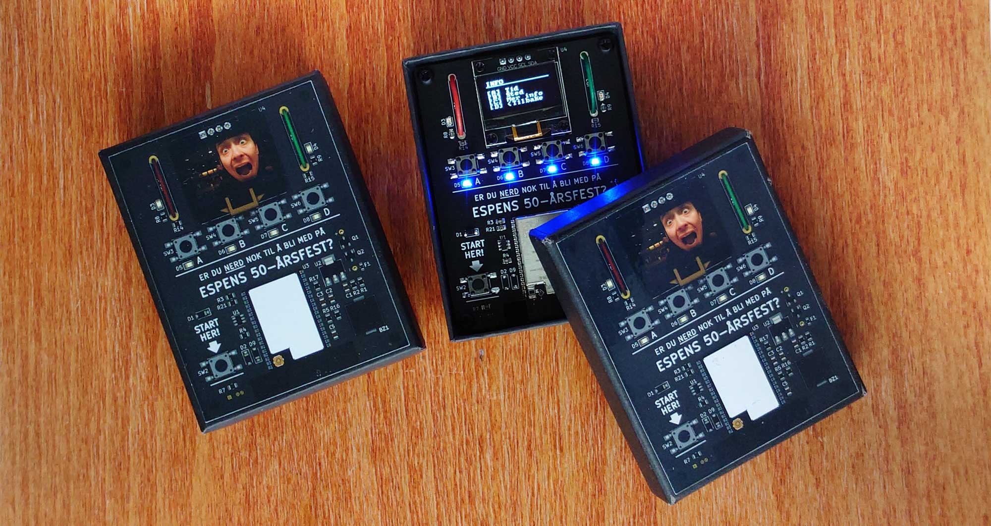
Final assembly of the invitation
To top it off I ordered a bunch of vinyl stickers for the lids, picturing a 3D rendering of the PCB.
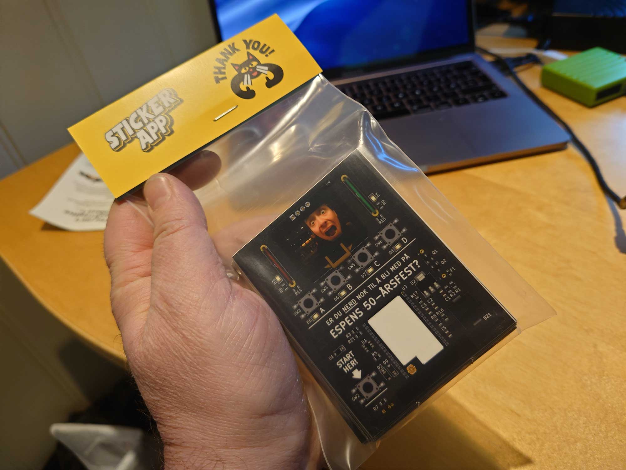
I got the stickers from stickerapp.no. They do custom sizes from your submitted graphics file. I edited the PCB image in Illustrator and placed an old facial of myself into the OLED frame.
Each invitation card took about an hour and a half to hand solder. I started with the battery holder before moving on to the microcontroller and the remaining components.
The OLED display was the last part to solder, after washing the PCB in an ultrasound cleaner.
My production run consisted of 10 boards. After assembling the PCBs, I started to prepare the boxes. An unpopulated board served perfectly as template for the placement of the standoffs. I added hot glue in each corner of the box, fastened the standoffs to the PCB with four screws and pressed them into the glue by applying pressure to the board for a couple of seconds.
The pre-cut foam pads that came with the boxes turned out to be perfect shock absorbers. They keep the batteries safely in place should the box be dropped or handled roughly.
Below is a video of the result. And, by the way: I have published the entire project on GitHub if you’re interested in the inner workings.