

I spotted a nice hobby project when my garage door was to be secured with an infrared light barrier.
Homemade gadgets are of lower quality and much more expensive. However, it’s a lot more fun!
Note that there is a Norwegian version of this posting published on Norwegian Broadcast Corporation’s Technology blog NRKbeta.
Access to low-cost online electronics services and shops has reduced the rationale to build anything yourself to zero. At the same time — and of the same reason — the options for hardcore DIY-freaks are better than ever before.
Infrared light barriers are useful in a lot of situations. They are part of the sensor system in car washers and alarm units, as well as door guards in shops, elevators and garages.
The technology
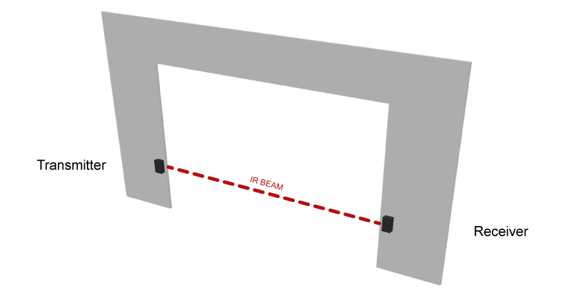
A standard garage door security barrier is formed by two small units that are mounted on each side of the gate. One is a transmitter, the other one a receiver. The receiver sends an active signal to the gate controller logic as long as the infrared (IR) signal is present so that the garage door can be safely closed.
If someone gets in the way while the garage door is on its way down, the receiver stops sending signals and the door goes back up. Many garage door openers have low-voltage interfaces intended for such sensors.
Technically, it’s simple: The transmitter has an infrared LED that emits an IR beam that is detected by a photo diode at the receiving end.
There’s lots and lots of examples on how to build infrared light barriers online. You will find detailed building instructions and even PCB layouts.
You will also find descriptions of how the signal from the ir-barrier circuit is modulated and transmitted to various brands of garage door openers, like this YouTube video.
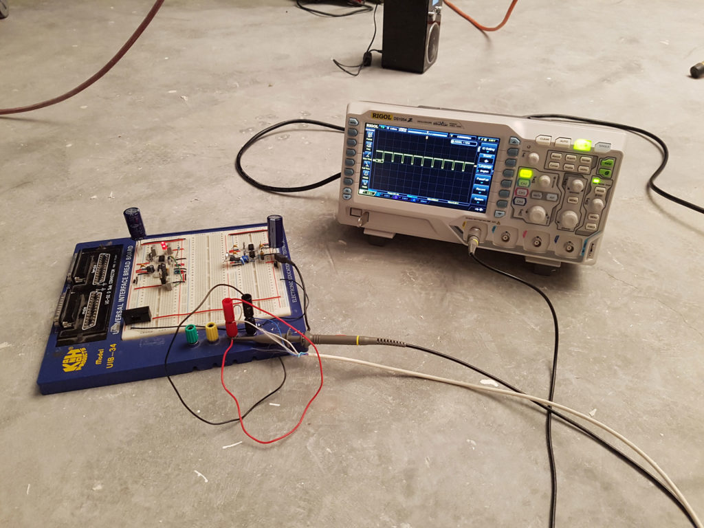
Experimental version, no soldering
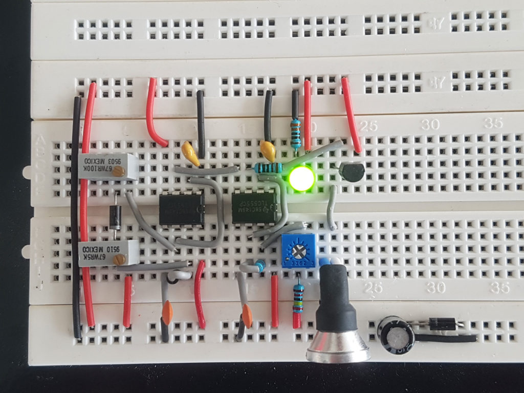
Initially, I did a couple of attempts wiring up the circuits on a breadboard, experimenting with various component values and transmission parameters.
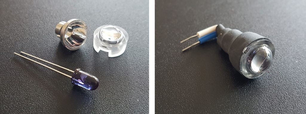
The light barrier would have to output sufficient power to work properly even in bright sunlight. Cheap IR diodes from eBay was not a good idea.
Instead, I found this high-power infrared LED at a well known supplier of electronic components. It works in bright daylight, even when installed several meters away from the receiver.
A blink for recognition
In addition to using a good transmitter diode, we have to modulate the IR beam. Both daylight and artificial light contain a substantial amount of infrared light. The receiver shouldn’t be fooled by arbitrary sources of ir-radiation, hence the light must stand out for the receiver to tell it apart.
In order to solve this problem, we let the transmitter diode blink a predetermined number of times per second. The receiver, on the other hand, is calibrated to recognize a narrow band around that specific frequency.
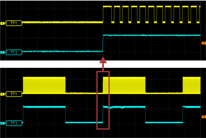
After some trial and error, I decided to modulate the LED two times: First with a carrier frequency of 38 kHz, then with a constant signal frequency of about 10 Hz.
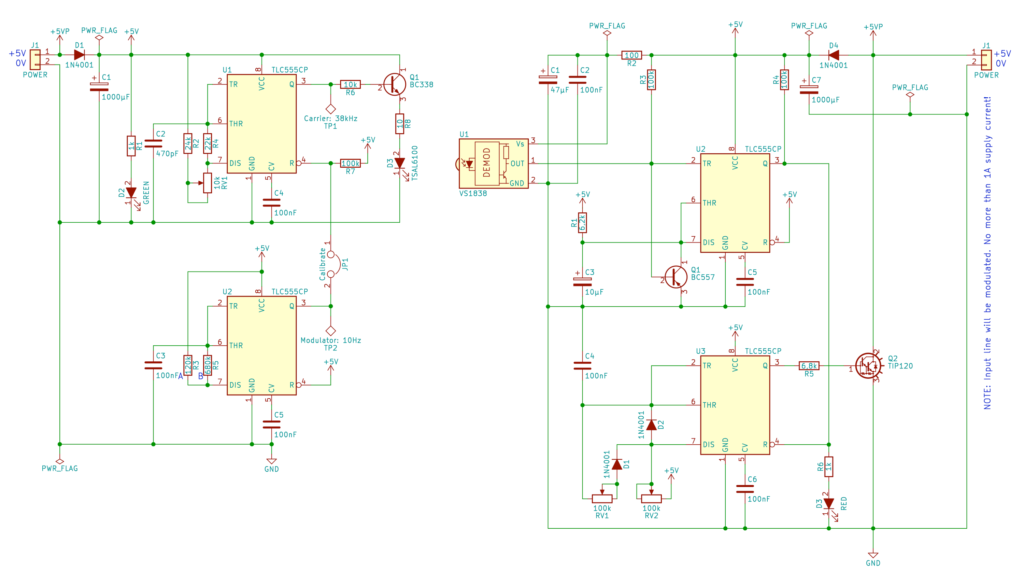
Circuit schematics
The last stage in the initial testing of the design, was to connect the rig to the garage door opener, og see if the transmission went as expected. A couple of forced emergency stops later, I felt ready to start drawing the schematics.
Proper schematics is imperative before continuing with the project. You need the drawings when making further adjustments and, of course, when you finally design the printed circuit board.
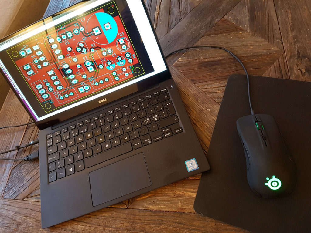
Times are changing, specially when it comes to so-called EDA software (Electronics Design Automations). Two decades ago, circuit and PCB design applications cost a fortune, ranging from a couple of hundred dollars for stripped-down versions up to several thousands for unlimited versions.
Nowadays, unbelievably good open source applications are freely available to anyone. Some of the commercial vendors have even released free versions of their software for educational or non-commercial usage. You’ve got several options, my personal favorite is KiCad.
Prototyping
With the proper schematics for the transmitter and the receiver at hand, I could now start designing the prototype. Time to crank up the soldering iron and pick up a couple of stripboards.
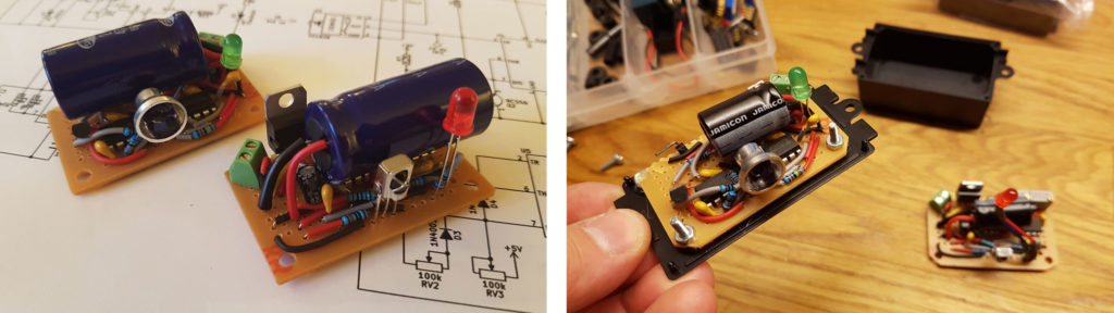
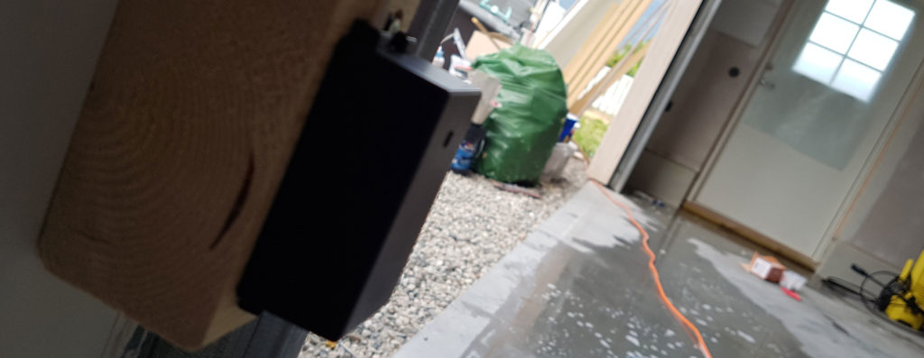
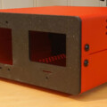
Each circuit card had to fit into a small plastic enclosure. The one I chose had mounting ears and wire holes.
Once I had a working prototype of the light barrier, I installed it to test and evaluate it for a couple of weeks. I needed to know that the design wouldn’t break over time.
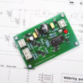
Designing the printed circuit board
I could have called it a day when my prototype turned out to work flawlessly. However, all no-nonsense electronics projects need a proper circuit board!
Having drawn the schematics, the remaining job was to find the right parts among several thousand pre-designed 3D component models and footprints.
With a bit of effort, I managed to squeeze all parts into a couple of small, five-by-three centimeter PCB’s. After part placement, the copper traces were routed and the silk screen printing adjusted a bit to avoid having ink on the solder pads.
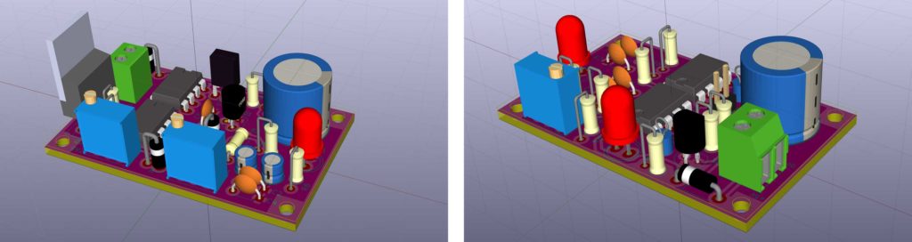
KiCad checks your design for mistakes, and gives you warning messages whenever the copper traces are wrongly routed, too close to each other, missing and so on. By the way, you will find many well-written tutorials on how to use KiCad online.
Once upon a time, projects like this had to be fulfilled at home, within reasonable economic limits. If you set out to produce only two or three circuit boards, you could forget about going to a PCB manufacturing house. It was simply far too expensive.
On the other hand, the process of transferring the PCB layout to the copper laminate was everything but a healthy business.
It involved toxic solder mask solution, sodium hydroxide and a aggressive mixture of hydrochloric acid and hydrogen peroxide.
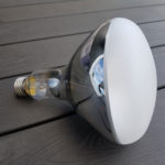
To top it all off, I used an intense ultra violet lamp for exposing the photoresist coatings and curing the solder mask. The lamp could easily cause severe sun burns. In other words: Making your own PCB’s was no walk in the park. Unless, of course, you’re talking about OSH Park (ba dum tss).
OSH Park
Various services have now emerged between the hobbyist and the PCB manufacturing houses. These services come self harmers like me to rescue by depriving us for any rational need for messing around with dangerous chemicals and UV-lights at home.
OSH Park is one of them, and their business model is as simple as it is ingenious.
Instead of dispatching the projects directly to the PCB manufacturing house one-by-one, the guys at OSH Park wait until they have collected enough orders to fill up a huge 18″ x 24″ panel. Hence, they can do multiple PCB’s in a single run. When they get the panel back, they literally break it apart and mail the final pieces to their customers.
This way the production cost is split between many customers. The price tag for each PCB is proportional to its size.
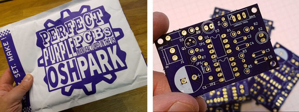
All I had to do, was to upload my KiCad project file and check the preview images of my PCB before completing my order. The rest worked out like a charm.

The price for six circuit cards (three of each) wasn’t even eligible for customs fee here in Norway. I paid just over 25 USD, including shipping. Of course, the light barrier PCB’s are pretty small, hence the low price.
The quality of the boards are still excellent, especially when it comes to the silk screen. Even my smallest font sizes became perfectly sharp and legible, which was really more than I expected. Impressive!
OSH Park produces their PCB’s in the US, and complies to the European Union’s RoHS directive. Watch the founder of OSH Park, James Neal, tell more about the concept in this episode of «Hardware Hangout».
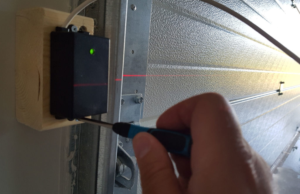
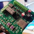
The final version
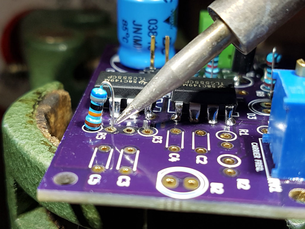
I guess soldering your own home-designed printed circuit board is the highlight of any such project. Provided I did a thorough job with my schematics, the soldering job shouldn’t be too demanding.
Once both the transmitter and the receiver was assembled and calibrated, the last part was to fit the circuit bards into the enclosures. Some adaptions were required.
I chose to glue the plastic lens on to the outside of the enclosure, instead of embedding it on the inside along with the reflector.
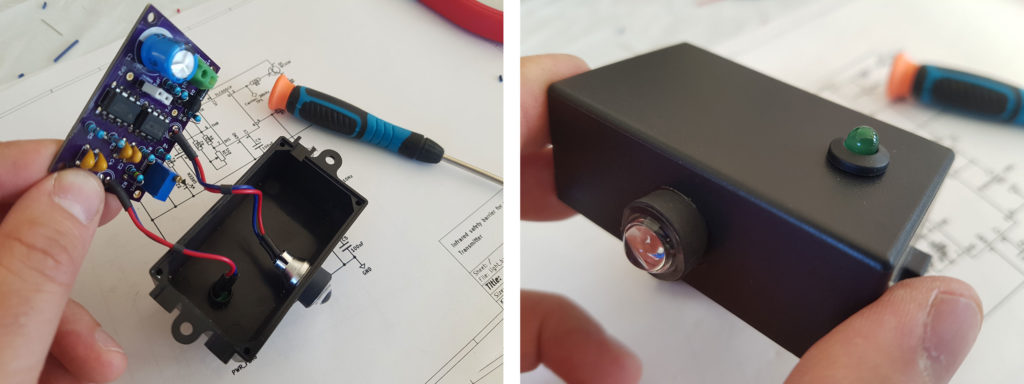
A nice 5mm LED holder for the indicator lights gave the front side of the enclosures a somewhat more professional look than just a drilled hole would do.
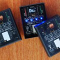
As long as it lasts…
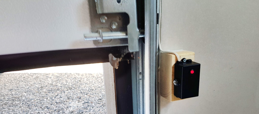
The previously mounted prototypes could now be replaced with my brand new, home made final version of the light barrier. The prototypes had worked without problems, but hopefully, the new ones will be even more stable.
It remains to be seen if the construction is up for some real long-term usage. I haven’t been too picky on calculating the component values, and am probably in for some trouble later on when one of the transistors gives in, or the IR LED burns out. Then I’ll be standing in front of a wide open garage, swearing because that §%#@$! door won’t close.
I don’t know exactly when that is going to happen, but from experience I would say it probably will occur some early winter morning in twenty centigrades below zero, with two grumpy kids in the back seat and me being in a hurry to get to work…
You can find my KiCad project on GitHub, and the PCB layouts are shared on OSH Park. Use entirely on your own responsibility, the schematics and artwork is released under GNU General Public License v3.0, with no warranties what so ever.

nice informative