How to build good looking front panels for premade electronics enclosures.
Most electronics makers dream of creating sleek, beautifully designed gadgets that look strikingly similar to something off Apple’s production line. Right?
Competing with Apple’s designers is admittedly a stretch. But if you find the right off-the-shelf enclosure, you’re still on track to creating something not too shabby. Building a nice custom front panel is more about planning and working with what you’ve got than just finding the perfect enclosure.
No matter how long you keep browsing, premade enclosures will have the wrong color, be missing vents, be made of the wrong material, be the wrong size, lack PCB mounts or wall mounts, and so on. At the end of the day, you’ll end up with some kind of compromise for your project.
On the other hand, relying solely on a 3D printer for your electronics enclosure can sometimes look a bit rough or unfinished. The solution? Combine the two approaches and get the best of both worlds.
Finding a box
When you don’t have the privilege to freely adapt your enclosure to your existing PCB or front panel layout, starting out with the enclosure instead can lead to unexpectedly good results.
If you use KiCAD or some similar software to create your own circuit boards, then that’s where you’re in full control! It is much easier to find a prefabricated enclosure that fits a yet-to-be-designed circuit board than the reverse.
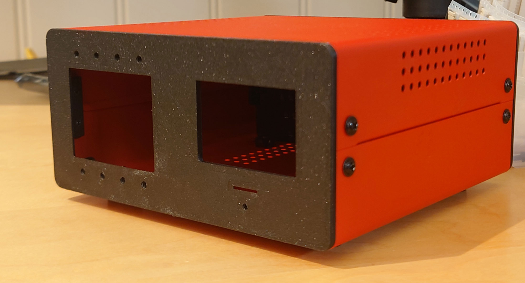
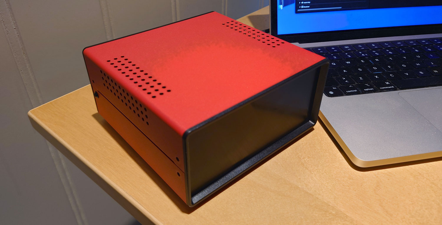
There’s a well-known mantra that says creativity thrives on constraints. By selecting this red aluminum enclosure as the basis, the direction was set. I focused on the black plastic end pieces, which can be replaced with custom 3D printed ones.
By going for 3D-printed panels, you can accommodate very tight tolerances. This allows for precise alignment of openings and holes to match the corresponding components on the PCB. All you need is the right CAD software.
Having this level of accuracy at your fingertips opens up a whole world of possibilities. You no longer have to rely on clunky snap-fit buttons or dashboard-style, screw-collared panel components. Instead, you can create pleasantly aligned holes and slots for your control panel items — while hiding the mounting hardware behind the cover.
Starting out in two dimensions
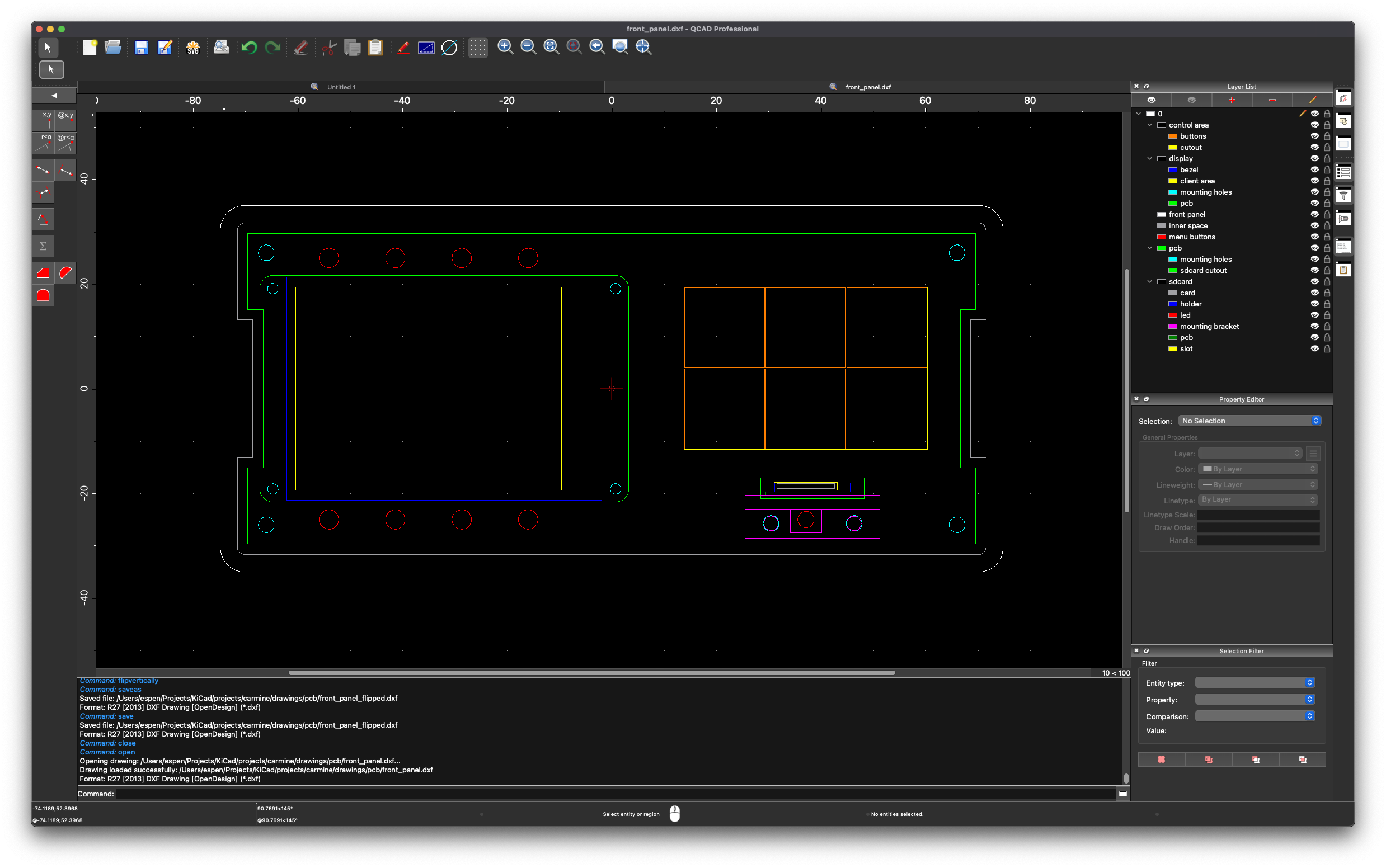
There are some good news and some bad news about my favorite 2D CAD program QCAD.
The good part is that the software is free, or – if you go for the pro version – inexpensive. The bad part is that you’ll have to spend time learning to use it.
QCAD is nothing like MS Paint. You need to be patient to learn it, but it will certainly be rewarding!
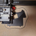
The process started by scanning the original end piece for the enclosure, then using the resulting image to produce an exact outline for the front panel. I did a write-up on this technique a couple of months ago.
I then started drawing the items to take into consideration when designing the front panel itself and also the PCB right behind it. I took care to get the accuracy down to at least 0.1 mm. Ideally, I find support in technical drawings of the components, but if they are not available, I grab my caliper and measure the components manually.
The SD card
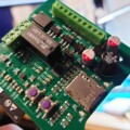
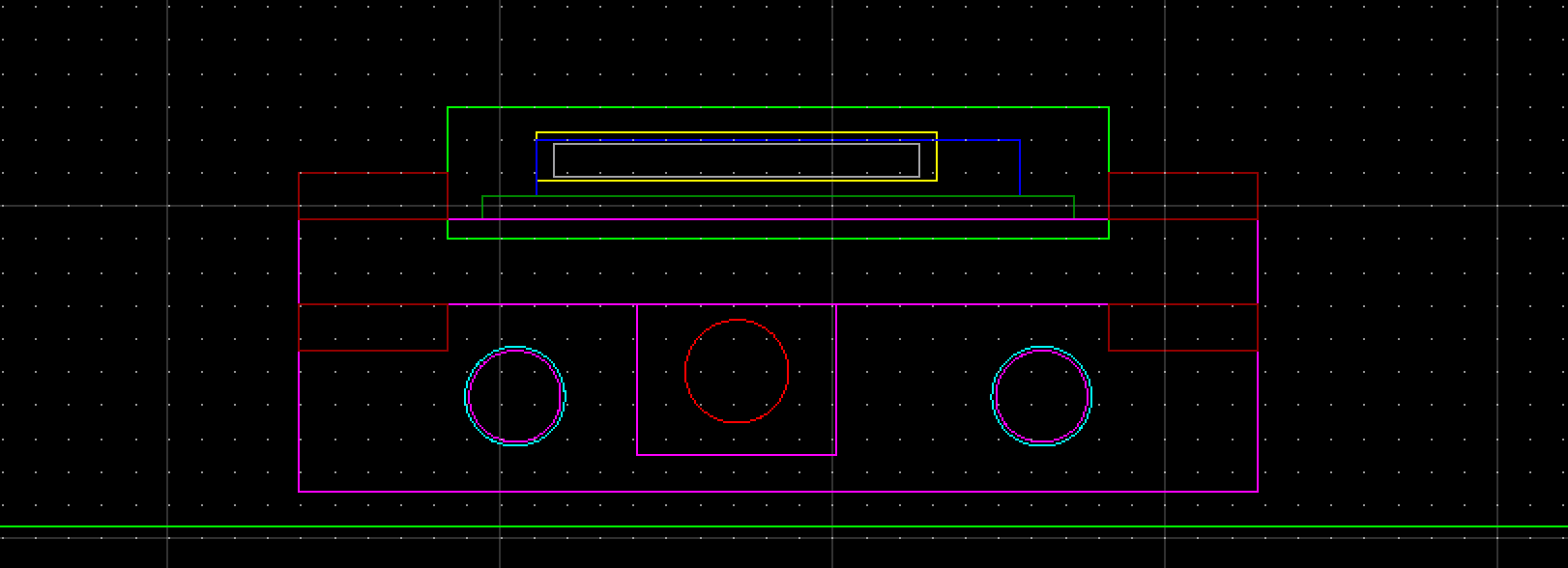
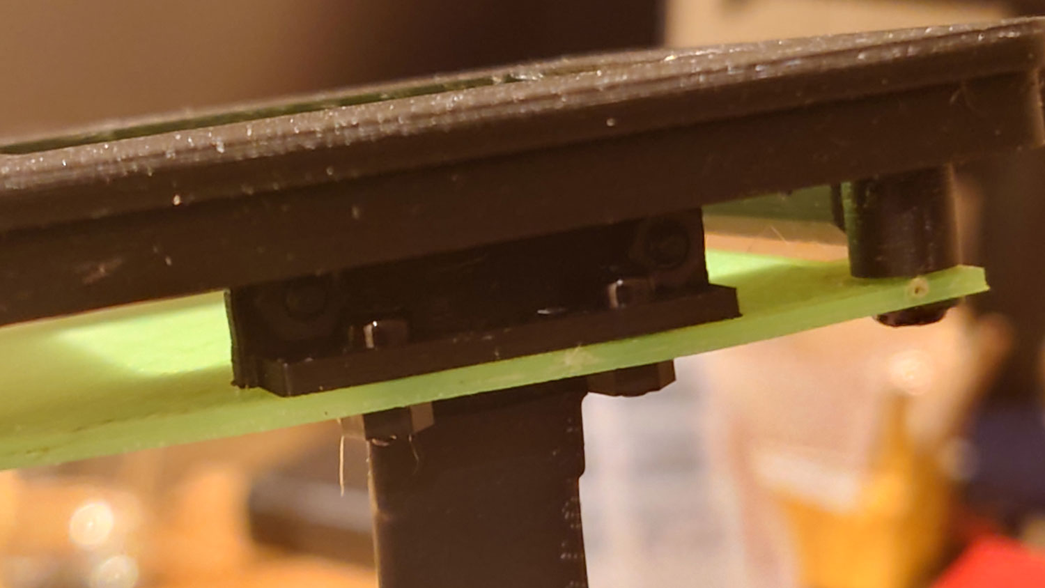
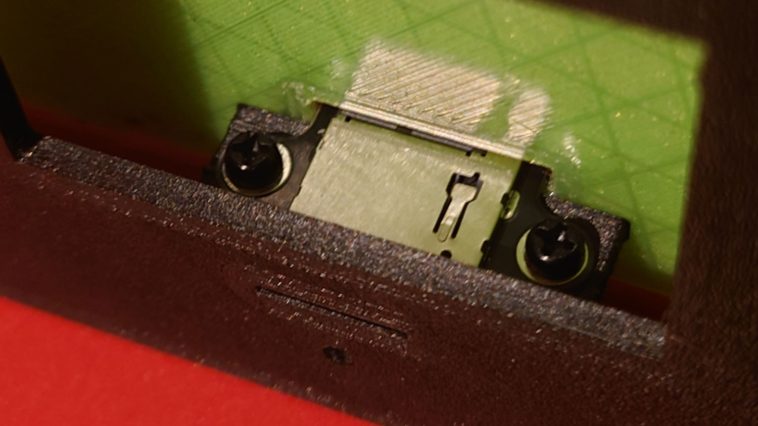
I wanted a prominently positioned SD card socket on the front panel — which meant doing some additional work. Precisely aligning the socket with the front panel opening required a custom mounting bracket, along with some extra drilling and PCB routing on the back side.
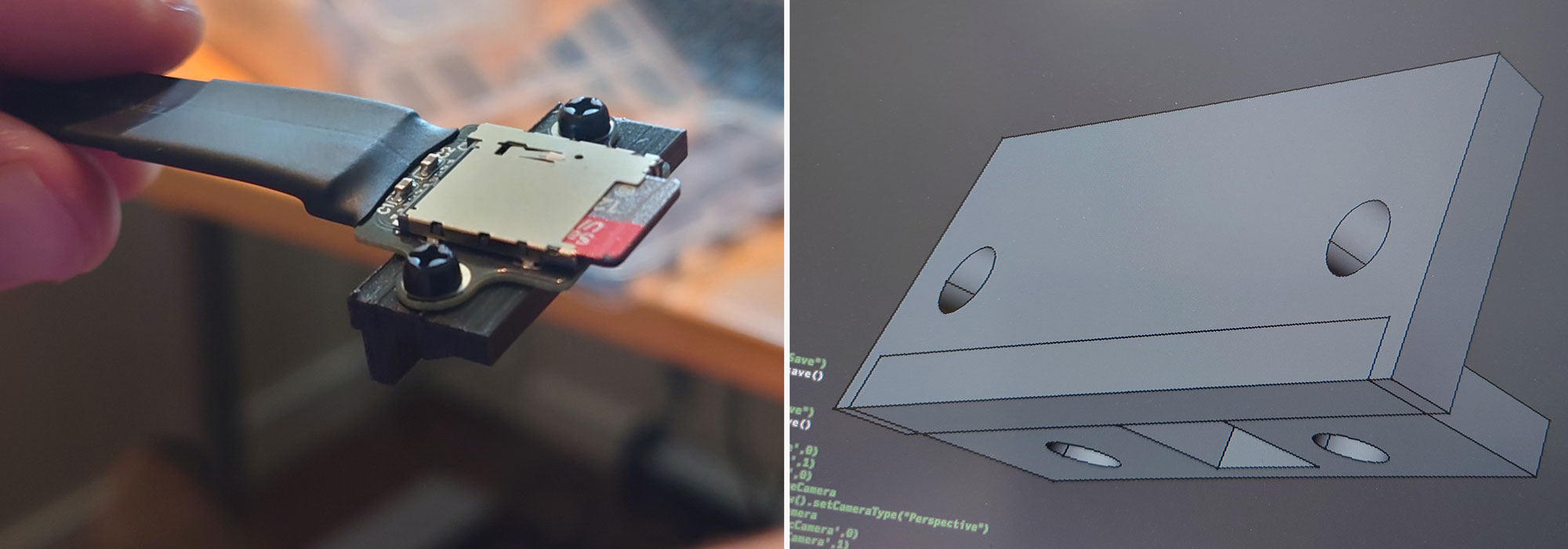
I intend to mount a Raspberry Pi as backend server inside the box. In order to bring the SD card slot to the front, I use a SD card extension adapter.
The card adapter has mounting holes, but it had to be oriented perpendicular to the PCB. Hence the angled bracket.
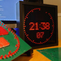
I sketched out the rest of the front panel along with cutouts for the LCD display and the buttons. I drew the outline of the PCB on a separate layer along with the SD card opening to make it easier to export the PCB’s edge cuts to KiCAD.
Going to third dimension
The QCAD drawing is a two dimensional representation of the front panel and the PCB. From now on, this file will serve as a common template for further work.
QCAD saves the artwork in DXF format. DXF is readable from both FreeCAD (for 3D design) and KiCAD (for PCB design).
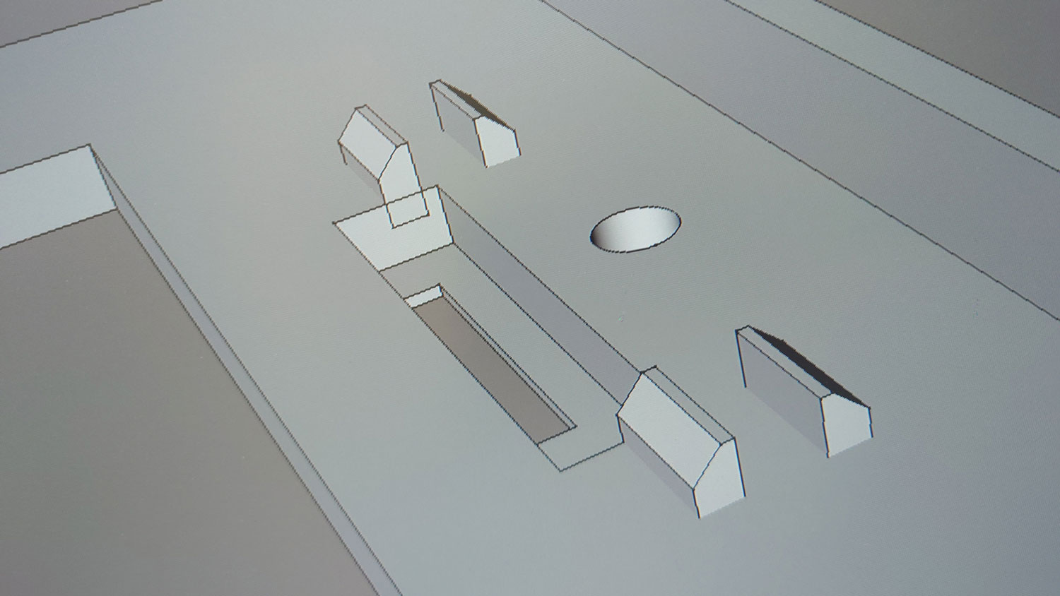
First things first: The custom mounting bracket for the SD card adapter was easy to draw in FreeCAD.
Importing the DXF file into FreeCAD works like a charm. All layers become nicely laid out in the tree view. You can either create sketches directly in the draft workbench, or just use the 2D paths as visual templates while drawing the sketches manually.
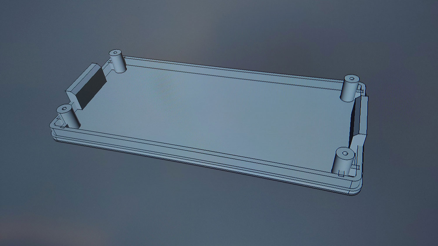
The first task in FreeCAD was to model the uncut panel plate. This will be the staring point for both the front and back panels.
The FreeCAD file for this intermediate version of the face plate is available for download from my GrabCAD profile, in case you should get hold of the same enclosure. Feel free to use the model as starting point for your own front panel.
Tweaking the cuts
Now, stick to the DXF file! If you need to make adjustments to the front panel layout, go back to QCAD, do the changes there first and re-import the new file in FreeCAD before altering the 3D model.
As long as the 2D and 3D files are in perfect sync, you’re ready to start working on the PCB in KiCAD.
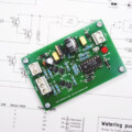
To test the placement of the SD card and the PCB edge cuts, I created and printed a dummy circuit board from the DXF. I made it 1.6 mm thick to mimic a standard FR-4 laminate.
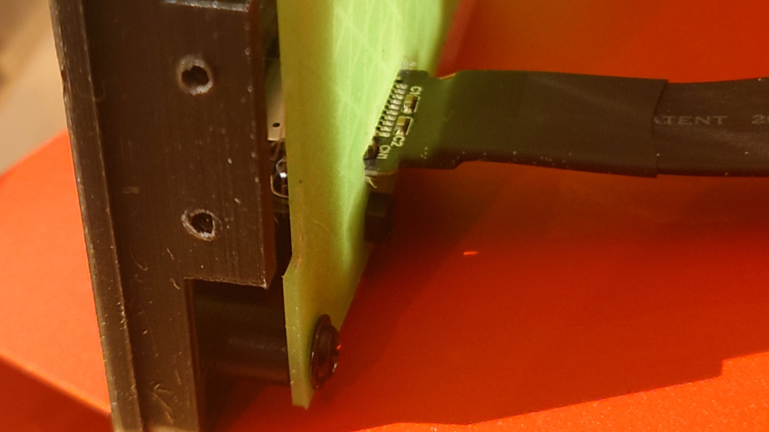
It took some tweaking to get the SD card slot just right — but once it was in place, it worked flawlessly.
Flush-mounting the display
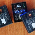
The display needed special attention. I selected a Waveshare 2.4 inch display Module for this project. The display’s client area measures about 50×39 mm while the bezel is approximately 60×43 mm.
To bring the display glass flush with the panel surface, the display sits in a recessed pocket at the back of the front panel.
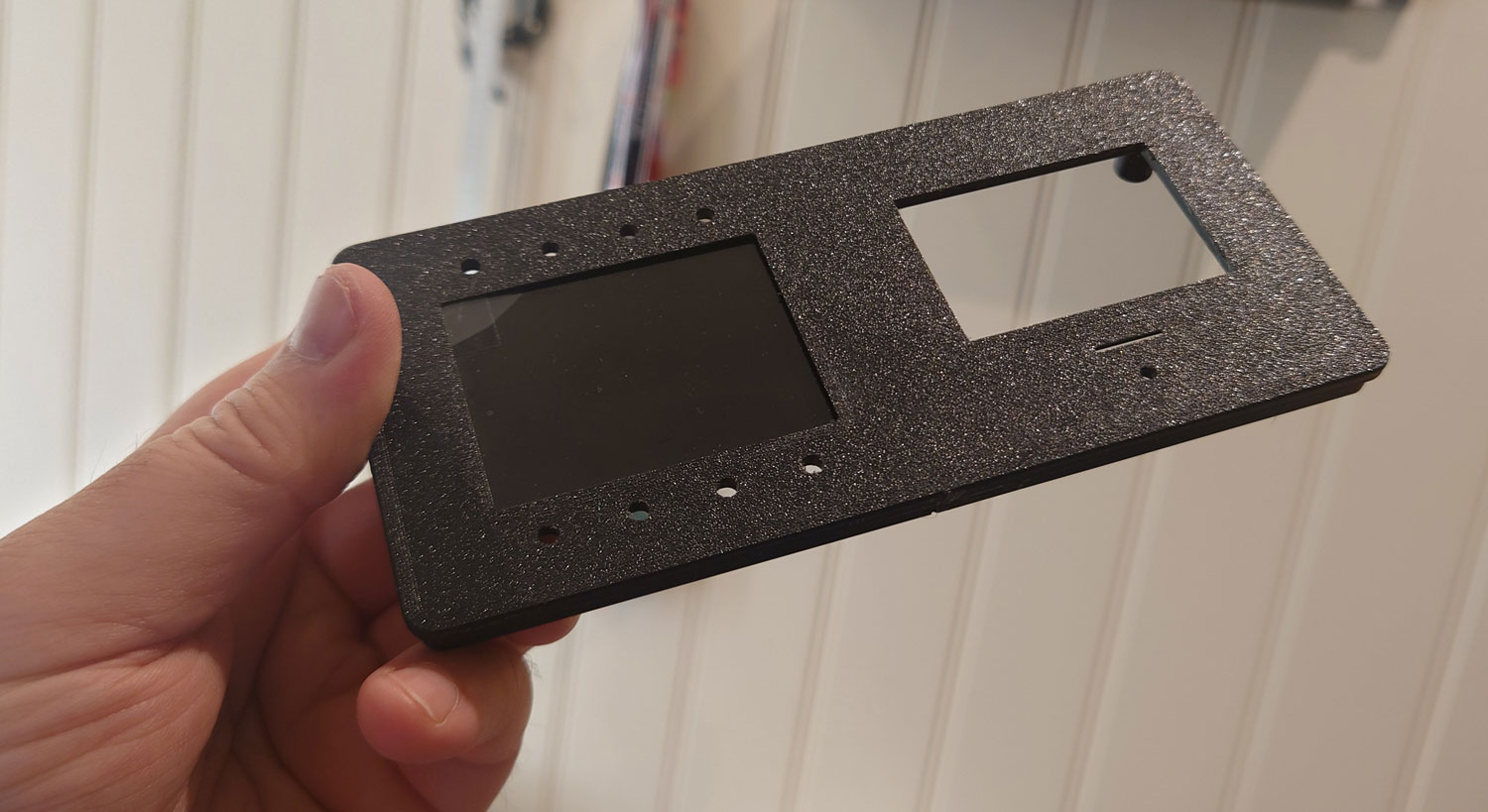
The pocket on the back side matches the size of the bezel, reducing the visible frame depth to just 0.5 mm — which creates a much cleaner and more polished look.
The display module is mounted to the PCB using standoffs that position it precisely within the pocket.
Eight menu buttons are placed along the top and bottom edges of the display. They’re standard tactile pushbuttons with shafts just long enough to protrude through the front panel.
Then there are six large, illuminated control panel buttons to the right of the display. They can be grouped tightly together, so one larger rectangular opening for them all will do.
Once again, the component placement needs to be accurate down to fractions of a millimeter — which is why the DXF file remains the primary layout reference. Placing the pushbuttons in KiCAD will be a breeze if you have an updated set of 2D drawings as reference.
Workflow in brief
- Find a nice enclosure with replaceable plastic panels or end pieces.
- Draw a layered outline of the panel with the PCB in 2D using your preferred CAD program, for example QCAD.
- Sketch out a preliminary layout for your front panel and decide where to put the mounting holes for the PCB.
- Calculate the required distance between the PCB and the front panel. This distance is typically dictated by the components with strict physical constraints or limited alternatives — in my case, the large push buttons.
- Start by drawing components requiring mounting assemblies (brackets, standoffs) and additional PCB milling.
- Then draw the smaller items. Feel free to browse for better alternatives if your current component doesn’t quite fit. Tactile push buttons, for example, are available in almost any size and height.
- Take care to draw the complete footprint of the front panel components. You will then be able to detect collisions if the layout becomes too tight.
- Import the 2D drawing into a 3D program, such as FreeCAD. Create the 3D model for the front panel.
- I you need to adjust the model, make the changes in 2D first, then re-import and amend the 3D model accordingly.