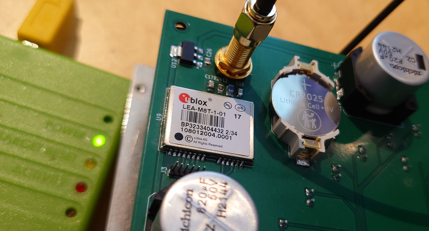
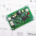
The u-blox LEA-M8T timing module is part of my my broadcast clock project. This is how I got it to work over i2c against ESP32 WROVER-E.
The LEA M8T module receives atomic clock signals from satellites, and supports a variety of GNSS systems. That makes it a perfect time reference for my clock, as it brings the accuracy down to only a few microseconds (finally, I’ll get the kids to school in time).
In comparison, NTP protocol typically provides an accuracy of tens of milliseconds when operating over the web.
Setup with ESP32
Programming u-blox modules can be a bit tricky. Even more so if you insist on doing it solely over i2c against u-blox’ interface.
Most online guides use u-center, which is u-blox’ own software for programming the devices. This is my attempt at getting the same result using the ESP32 only.
For my project, I use ESP32 WROVER-E with Espressif’s IDF framework. The u-blox chip is set for 400kHz i2c transmission speed.
I’ll describe how I set up i2c against u-blox LEA M8T specifically, even though I expect other u-blox modules to have similar interface. I hope my writing will work as a general rough guide on how to set up the communication protocol.
Stretching the i2c clock — and my patience
I was about to advice against using the new i2c driver in the IDF SDK. The driver simply wouldn’t work against the u-blox module due to a bug, and a bug fix was not in place at the time of programming.
I believe the failure had to do with the u-blox module doing so-called clock stretching, which seemed to be poorly handled by the new driver. It gave tons of hardware timeout failures, lost packages, and damaged data blocks.
As a side note, I got it to partially work with the new driver by reducing the i2c clock speed to about 5 kHz. That presumably reduced the need for clock stretching enough to get at least a few packages through. Nevertheless, I still had timeout errors on the ESP32, so it continues to be a no-go.
A promising bug fix found its way into the IDF repository not long ago, so the new driver might be fine now. But I’m not in the mood for another rewrite of the source code, so I’ll stick to the legacy driver for now.
Setting up the bus
Below is my diagram for the LEA M8T module, as designed into my broadcast clock project. Pin 1 and 2 is the i2c interface, data and clock lines, respectively. They are wired against GPIO 21 and 22 on the ESP32.
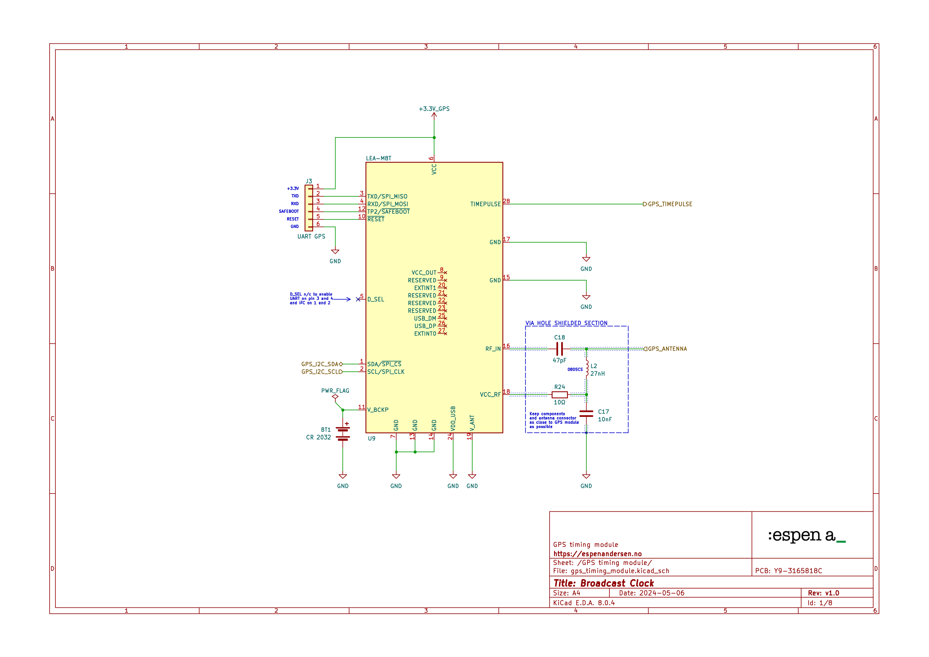
First things first: Setting up GPIO pins and Configuring the ESP32 to act as the master device. The u-blox LEA M8T only operates in slave mode, so mode has to be set to I2C_MODE_MASTER. Here, I also set the clock speed, going for max speed, clk_speed = 400 kHz.
i2c_config_t conf;

memset( &conf, 0x00, sizeof( i2c_config_t ) );

conf.mode = I2C_MODE_MASTER;
conf.sda_io_num = GPIO_NUM_21;
conf.sda_pullup_en = GPIO_PULLUP_ENABLE;
conf.scl_io_num = GPIO_NUM_22;
conf.scl_pullup_en = GPIO_PULLUP_ENABLE;
conf.master.clk_speed = 400000;
ESP_ERROR_CHECK( i2c_param_config( I2C_NUM_0, &conf ) );
ESP_ERROR_CHECK( i2c_driver_install( I2C_NUM_0,
                                     I2C_MODE_MASTER,
                                     0, 0, 0 ) );

i2c_set_timeout( I2C_NUM_0, 1000000 );
The u-blox module has built-in pull-ups, so setting GPIO_PULLUP_ENABLE on lines 7 and 9 is probably not strictly necessary.
On line 16 comes the magic setting that fixes the above mentioned problem with timeout due to clock stretching. If this setting is given a high value, it keeps the i2c line from causing an interrupt whenever the CLK line is kept low for an extended time period.
This parameter is given as number of APB (Advanced Peripheral Bus) clock cycles. The APB clock on the ESP32 is 80 MHz, so a value of 1.000.000 gives us 1.000000 / 80.000.000, or a timeout value of 12,5 ms.
Saving the config or not
Basically, there are two approaches to consider when setting up the LEA M8T. Both strategies entail sending a series of configuration messages to the module.
The first approach is to configure the module as part of the build process. The GNSS module is programmed in a separate step, saving the configuration data to non volatile memory. The saved configuration is then retrieved and activated every time the module boots up.
This relieves the MCU of some of the burden of having to configure the M8T at startup. Besides, programming the u-blox module is a pretty straight forward process if you use the u-center software.
The second approach is letting the MCU send the complete setup sequence to the module at every boot, instead of relying on a setup saved in advance.
I prefer the latter, as it doesn’t introduce the extra build step of programming the GNSS module individually. The configuration is done in one place, period.
Getting ready for data transmissions
One of the differences between the new and the old i2c driver is that the old one leaves it to you to address the device and set the read/write bit. The new one takes care of such details under the hood.
Below is my transmit function. The variable msg is an array of uint8_t of buflen size, holding the UBX message to send:
const uint8_t i2c_address = 0x42;
i2c_cmd_handle_t cmd = i2c_cmd_link_create();
i2c_master_start( cmd );

// Address the device and set the R/W bit
i2c_master_write_byte( cmd,
                       ( i2c_address << 1 ) |
                       I2C_MASTER_WRITE,
                       true );

// Send the UBX message
i2c_master_write( cmd, msg, buflen, true );

i2c_master_stop( cmd );

// Send prepared data to the LEA M8T
esp_err_t res = i2c_master_cmd_begin( I2C_NUM_0,
                                      cmd,
                                      1000 );
i2c_cmd_link_delete( cmd );
The default address i2c_address of the u-blox LEA M8T is 0x42, which, in reality, is a seven bit value (binary 1000010).
The first byte to send to the unit is the device address and the read/write bit. 0 means ‘write’, 1 means ‘read’. The two bitfields are assembled to one byte, of which the least significant bit is the read/write flag. The next seven bits holds the device address.
LEA M8T messages
You’ll find a complete overview over the available NMEA and UBX messages in the protocol specification from u-blox.
Some messages can be polled at preset intervals. By setting its poll rate, you can decide how often you want an updated message. The poll rate can be set for each message. A poll rate of 0, the message is disabled.
We need to disable NMEA messages. That’s done by sending the UBX_CFG_MSG message.
Fletcher’s checksum
Each UBX message starts with the sync characters 0xb5 and 0x62, and ends with a two-byte checksum, the 8 byte fletcher’s checksum of the message (not including the sync characters).
You must pass a valid checksum along with every message. Otherwise, the GNSS module will ignore it. Likewise, you should always validate the checksum of received messages as well, before processing them.
It is easy to calculate fletcher’s sum. The fletcher8 function digests the input buf, produces the fletcher’s checksum for len characters and places the two-byte result into sum:
void fletcher8 ( unsigned char *buf,
                 size_t len,
                 unsigned char *sum ) {
  sum[ 0 ] = 0x00;
  sum[ 1 ] = 0x00;
  for( size_t i = 0; i < len; i++ ) {
    sum[ 0 ] = ( sum[ 0 ] + buf[ i ] ) % 256;
    sum[ 1 ] = ( sum[ 1 ] + sum[ 0 ] ) % 256;
  }
}
Initial setup
The u-blox module has an initial setup that may or may not fit your needs. One of the gotchas in that regard, is that once the chip is powered up it will start sending a continuous stream of NMEA 0183 messages by default. As a consequence, you may want to “de-caffeinate” the chip a bit.
To disable the NMEA messages, you must do them one at a time. I simply iterated over an array with all NMEA message codes, explicitly turning each one of them off.
// NMEA messages to be disabled
const uint8_t messages[][2] = {
      {0xF0, 0x0A}, // DTM
      {0xF0, 0x44}, // GBQ
      {0xF0, 0x09}, // GBS
      {0xF0, 0x00}, // GGA
      {0xF0, 0x01}, // GLL
      {0xF0, 0x43}, // GLQ
      {0xF0, 0x42}, // GNQ
      {0xF0, 0x0D}, // GNS
      {0xF0, 0x40}, // GPQ
      {0xF0, 0x06}, // GRS
      {0xF0, 0x02}, // GSA
      {0xF0, 0x07}, // GST
      {0xF0, 0x03}, // GSV
      {0xF0, 0x04}, // RMC
      {0xF0, 0x0E}, // THS
      {0xF0, 0x41}, // TXT
      {0xF0, 0x0F}, // VLW
      {0xF0, 0x05}, // VTG
      {0xF0, 0x08}  // ZDA
    };

for( size_t i = 0;
     i < sizeof( messages ) / sizeof( messages[ 0 ] );
     ++i )
{
  // UBX_CFG_MSG message
  uint8_t msg[ 11 ];
  msg[ 0 ] = 0xb5; // UBX sync char 1
  msg[ 1 ] = 0x62; // UBX sync char 2
  msg[ 2 ] = 0x06; // Message class (CFG)
  msg[ 3 ] = 0x01; // Message id (MSG)
  msg[ 4 ] = 0x03; // Length, LSB
  msg[ 5 ] = 0x00; // Length, MSB
  msg[ 6 ] = messages[ i ][ 0 ]; // NMEA MSG cls
  msg[ 7 ] = messages[ i ][ 1 ]; // NMEA MSG id
  msg[ 8 ] = 0x00; // Rate, 0 (disable message)

  // Write checksum to bytes 9 and 10
  fletcher8( &msg[ 2 ], 7, &msg[ 9 ] );

  // Send message over i2c
  i2c_cmd_handle_t cmd = i2c_cmd_link_create();
  i2c_master_start( cmd );

  // Transmit device address and read/write bit
  i2c_master_write_byte( cmd,
                         ( m_i2c_address << 1 ) |
                           I2C_MASTER_WRITE, true );

  // Transmit message
  i2c_master_write( cmd, msg, sizeof( msg ), true );

  i2c_master_stop( cmd );

  // Commit
  i2c_master_cmd_begin( I2C_NUM_0, cmd, 1000 );

  // Clean-up
  ESP_ERROR_CHECK( i2c_cmd_link_delete( cmd ) );
}
After quelling the NMEA message storm, you can set up the LEA M8T to send individual messages at various rates. As an example, you may want UBX_NAV_UTCTIME to be sent more frequently if it serves time critical functions in your app, as opposed to UBX_NAV_SAT, that updates a user information panel.
Setting the message rate
It’s done with the UBX_CFG_MSG configuration message, the same one as I used to disable NMEA, However, there’s another message we must know of as well.
UBX_CFG_RATE sets how frequently the GNSS module should collect satellite data, and also how many such measurements to await before calculating actual position, speed and time.
Since my clock project’s setup relies on a fixed-positioned antenna, there’s no need for high measurement and solution rates. In fact, going for fewer solutions based on a larger number of measurements can even benefit the accuracy of the system. Slower rates will eventually reduce processing time on your system.
I ended up with a 100 milliseconds measurement rate, and eight measurements per solution. As a consequence, I now have one solution every 800 millisecond, which will be the base rate for navigation messages.
But still, the UBX_CFG_RATE message doesn’t dictate the message flow alone. Equally important is the UBX_CFG_MSG settings, as it adds a multiplier for each navigation message. So, if the multiplier value is 0, the message will be disabled, 1 means 800 milliseconds on this setup, 2 means 1,6 seconds and so on.
// UBX_CFG_RATE message
uint8_t ubx_cfg_rate[ 14 ];

ubx_cfg_rate[ 0 ] = 0xb5; // UBX sync char 1
ubx_cfg_rate[ 1 ] = 0x62; // UBX sync char 2
ubx_cfg_rate[ 2 ] = 0x06; // Message class (CFG)
ubx_cfg_rate[ 3 ] = 0x08; // Message id (RATE)
ubx_cfg_rate[ 4 ] = 0x06; // Length, LSB
ubx_cfg_rate[ 5 ] = 0x00; // Length, MSB

// Casting multi-byte integers directly into the
// message buffer only works as long as the
// compiler target has little-endian byte order,
// like the ESP32

// Measuring rate (100 ms)
*reinterpret_cast<uint16_t *>( &ubx_cfg_rate[ 6 ] ) = 100;

// Navigation rate (8 cycles)
*reinterpret_cast<uint16_t *>( &ubx_cfg_rate[ 8 ] ) = 8;

// Time reference (UTC time)
*reinterpret_cast<uint16_t *>( &ubx_cfg_rate[ 10 ] ) = 0;

// Write checksum to bytes 12 and 13
fletcher8( &ubx_cfg_rate[ 2 ], 10, &ubx_cfg_rate[ 12 ] );

// Transmit message (see code above)
// ... ... ...

// // UBX_CFG_MSG
uint8_t ubx_cfg_msg[ 11 ];

ubx_cfg_rate[ 0 ] = 0xb5; // UBX sync char 1
ubx_cfg_rate[ 1 ] = 0x62; // UBX sync char 2
ubx_cfg_rate[ 2 ] = 0x06; // Message class (CFG)
ubx_cfg_rate[ 3 ] = 0x01; // Message id (MSG)
ubx_cfg_rate[ 4 ] = 0x03; // Length, LSB
ubx_cfg_rate[ 5 ] = 0x00; // Length, MSB

ubx_cfg_rate[ 6 ] = 0x
Getting the timing right
When writing the code to communicate with a GNSS timing module, timing really is crucial (!), which of course is why you’d want to wire the GNSS’ TIMEPULSE pin to the ESP32. That gives you an interrupt source that will trig exactly at the moment a new second begins, referred to as “top of second”, typically within a few nanoseconds’ margin of error.
All you need to do in the interrupt handler, is to record the current number of clock cycles, using the xthal_get_ccount() function. Below is my handler from the broadcast clock C++ source:
void broadcast_clock::lea_m8t::
isr_timepulse_handler( void *arg ) {
  UBaseType_t intstat = taskENTER_CRITICAL_FROM_ISR();
  lea_m8t *inst = static_cast<lea_m8t *>( arg );
  inst->m_timepulse_cc = xthal_get_ccount();
  taskEXIT_CRITICAL_FROM_ISR( intstat );
  lea_m8t_timepulse_queue_item_t tp_item = {
    lea_m8t_timepulse_message::timepulse, nullptr };
  xQueueSendFromISR(
    inst->m_timepulse_queue,
    &tp_item,
    nullptr );
}
I record the cycle count inside a critical section, to make absolutely certain that no time slicing occurs at this stage. Hence, as soon as the cycle count is safely stored, I exit from the critical section and enqueue a timepulse task message that will be handled in context.
Immediately after the TIMEPULSE, the LEA M8T will send a UBX_TIM_TOS (top of second) message with the current time stamp. This is where you’d want to adjust the system time. This message will be handled shortly after the TIMEPULSE — but no worries. The cycle count you stored got you covered.
When handling the top of second message, microseconds since TIMEPULSE can easily be calculated from the number of elapsed clock cycles. This delay can thus be accounted for when setting the precise system time.

