
Ever since I laid eyes on a real broadcast clock, I knew I had to get one, with automatic time keeping over NTP or via satellites. That calls for another hairy ESP32 electronics project!
First of all, the project can be found on my GitHub profile. It includes the complete source for both hardware and firmware. I have released it under GNU General Public License V3.
- The project on GitHub: https://github.com/espena
- Parts list: bill_of_material_broadcast_clock.xls
Project features
In modern life, timekeeping has become an inevitable necessity. What should be less inevitable, is the need for setting the time manually on multiple clocks around the house after every power outage. Not to mention adjusting for daylight saving time twice a year. So, NTP is your friend, along with satellite receivers.
These are the features I’ve implemented in my project:
- NTP time synchronization
- Satellite clock synchronization (GPS)
- NTP server for syncing other clocks over LAN
- Browser configurator, available over WiFi
- 24 and 12 hour time format
- Automatically adjusts for daylight saving time
- Adjusts display brightness to ambient light
- Stop watch with browser interface
- Countdown timer with browser interface
NTP/GPS wall clock that rocks
The broadcast industry did away with manual and inaccurate clocks a long time ago. Keeping track of assigned air time is paramount to prevent chaos. All broadcasters need studio clocks that are perfectly in sync with one another.
These clocks use internal or external network time servers (NTP) or even satellites to maintain precise timing. After setting the right time zone (with or without daylight saving time), no more interaction is needed to maintain great accuracy.
OK, I know there are lots of clocks for sale with time server protocols, DCF77 radio sync and whatnot. However, I have issues with most of them. They just don’t match the cool factor of a proper broadcast clock. Additionally, I have no simple way to make them work the way I like, and most of them are physically too small for my preferences.
Besides, the price tag for the professional ones are way over my budget. So, luckily, this appeared to be a very nice candidate for an ESP32 summer DIY electronics project.
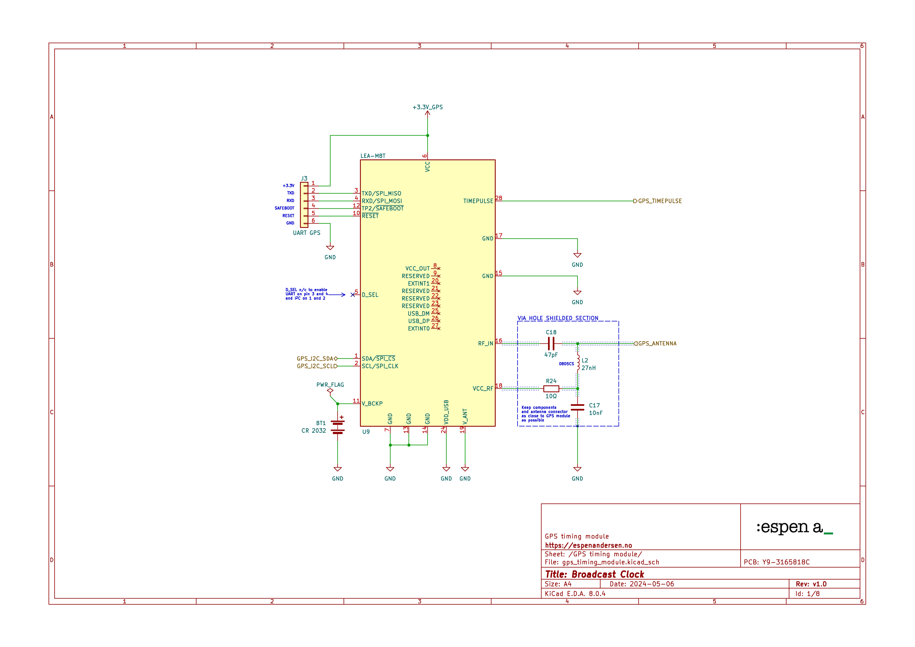
I figured I wanted two alternative time sources. In addition to using NTP, I implemented a satellite time receiver. I decided to go for the u-blox LEA M8T GNSS/GPS receiver chip along with an active antenna connection. Technically, the accuracy will be within 30 ns, as opposed to NTP that is in the tens of ms range at its best over www. Anyhow, you’d be a time nut to appreciate the enhanced precision you get with the satellite receiver.
I did a separate posting on how I programmed the ESP32 to communicate with the M8T module.
The clock enclosure
When browsing for a proper electronics enclosure, I hardly ever find exactly what I’m looking for at specialized vendors. Injection molded plastic or die-cast aluminum enclosures tend to be either too tacky or too expensive. Oftentimes I end up looking elsewhere, because a little creativity can take you far.
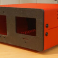
Actually, it was pretty easy to find the perfect wall clock enclosure. And the price tag was pleasant. It turned out that IKEA, the Swedish furniture giant, had exactly what I was looking for. Their “Sannahed” photo frame has the perfect size and appearance. It has a black, elegant finish. It is deep deep (6 cm), square-shaped and has the right size (25×25 cm).
The frame’s depth made it possible to fit the entire PCB with components inside, even leaving some air space for more effective heat dissipation.
I swapped the plexiglass front for a darkened, transparent 4mm acrylic plate intended for LED screen covering. That really made the whole thing stand out. To top it off, I got a local engineering company to machine a custom aluminum back plate for me.
Don’t be cheap!
I prefer dot matrix clock to traditional 7-segment numeric clocks. So I decided to use old-fashioned LEDs in this design.
That gave me full control of the display height and appearance. And it made it easier to match the colors of the smaller segments with 3mm LEDs, the larger ones with 5mm LEDs and the minute dial.
Because this is a DIY electronics project, and I don’t have a pick and place robot, hole mounted is king. They will stay in position during hand soldering, and replacing a single one is easier. The latter proved to be a good thing, since my stupid decision to go for el cheapo LEDs made it necessary to desolder and replace a bunch of them afterwards. So, buy proper LEDs!
Drawing the broadcast clock
Knowing the exact measurements of the enclosure, I started drawing the broadcast clock dial and back panel in QCAD, an excellent open source 2D CAD application.
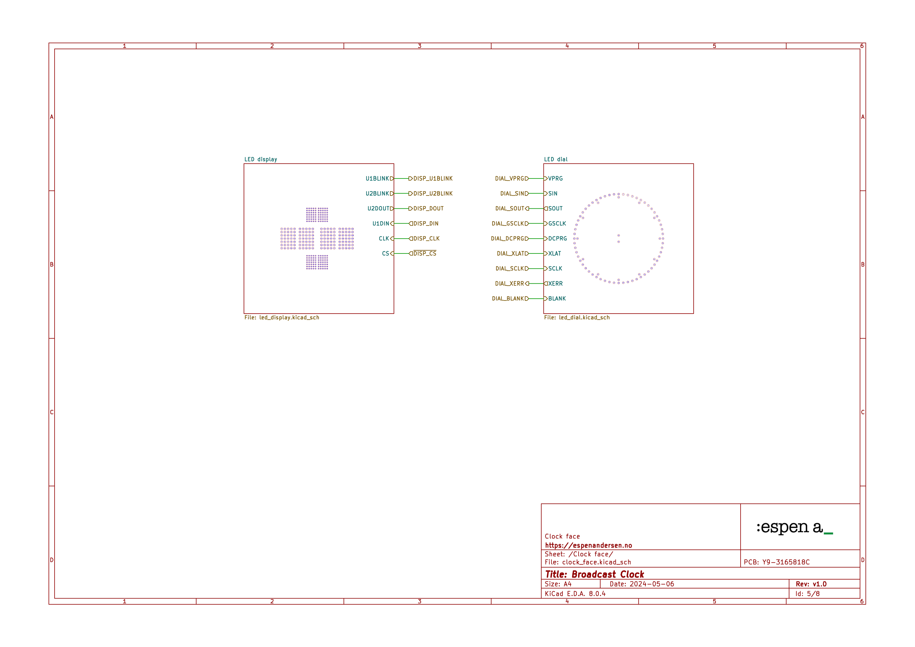
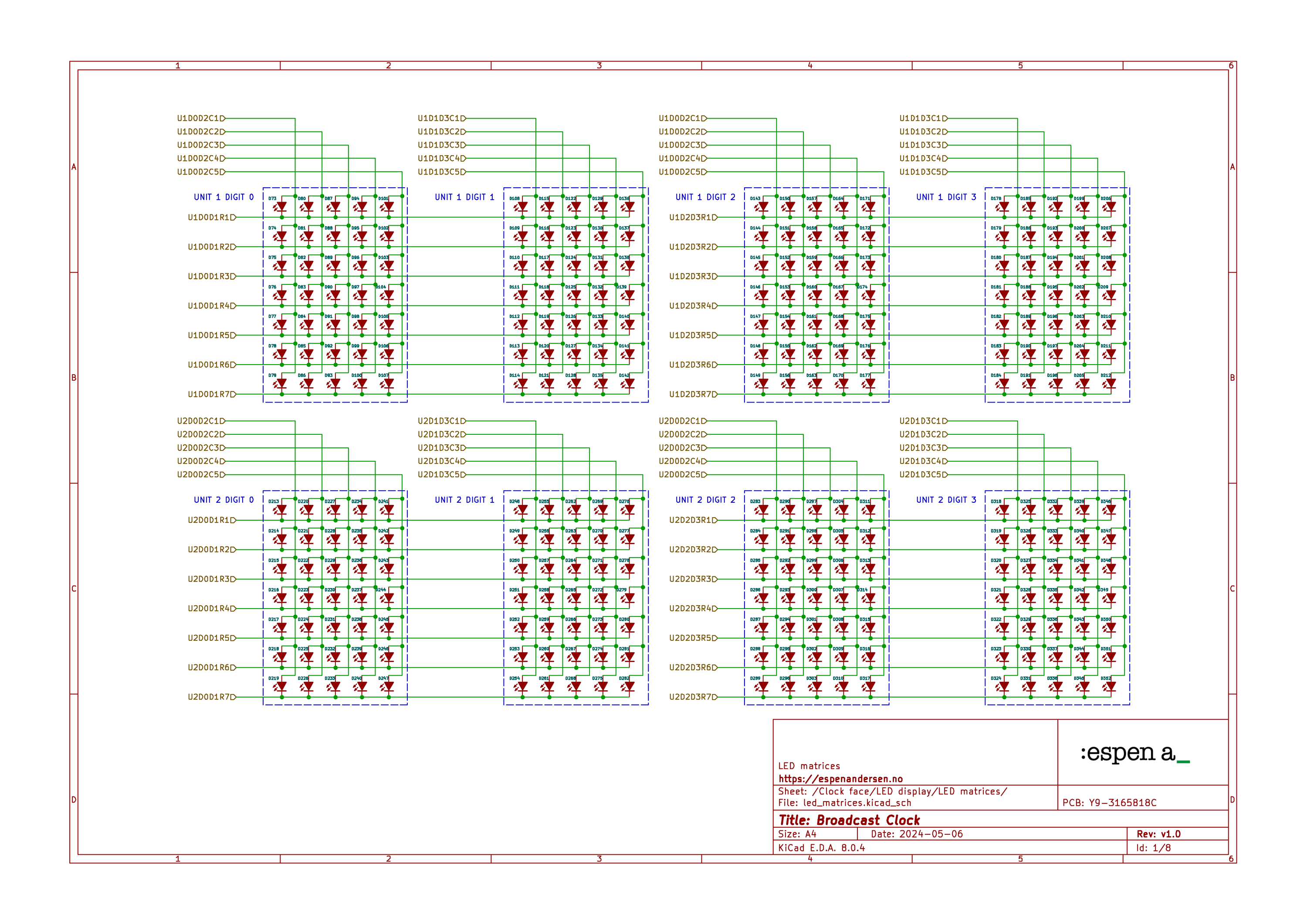
I wanted 60 second ticks along the outer edge of the dial, plus 12 ticks along the inner as hour markers. In the middle of the dial’s circle, I’d like to place three rows of alphanumeric characters.
The main display should be located in the very middle, with four large characters showing hours and minutes.
Two smaller displays, each with two characters, went above and below the main display. The upper one will show meridiem (AM/PM) for 12 hour time format and the lower will show seconds.
I started out in QCAD by drawing the board edges to exactly match the inside measurements for the IKEA frame. Then, by using the tools available in QCAD, I laid out the LEDs for the dial and the display matrices.
From QCAD to KiCAD
Each character is five dots wide by seven dots tall. With four digits, dial and time separator colon, that’s 354 LEDs all together.
Now it’s time to fire up my all time favorite software KiCAD and start drawing schematics for my electronics project.
I use QCAD partly because it is scriptable. That makes life a lot easier when exporting the artwork to KiCAD for PCB routing.
KiCAD’s file formats are text-based, so generating the component placement in QCAD as a drop-in text block is easy. The text block can then be inserted directly into KiCAD’s PCB file using a text editor.
The QCAD script can be found at drawings/regen_led_layout.js in the project’s GitHub repository.
I organized the various parts of the broadcast clock face into separate layers to allow for assigning adequate component designators. I then matched these designators with the schematic.
Working the clock in KiCAD
I’ve usually gotten by with a single sheet of schematics for most of my projects. Both my dual-button doorbell and my ultimate invitation card had single-page diagrams.
This time, a single page approach wouldn’t cut it, there’s just too much going on in this wall clock. Splitting the schematics up in what developers would call a separation of concerns seemed reasonable. KiCAD has a concept called hierarchical sheets, which, in essence, groups the various parts of your design into logical, single-sheet units.
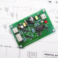
The first page of the schematic shows the outline for the whole electronics project. You can then drill down on each block to get the details behind each section or part.
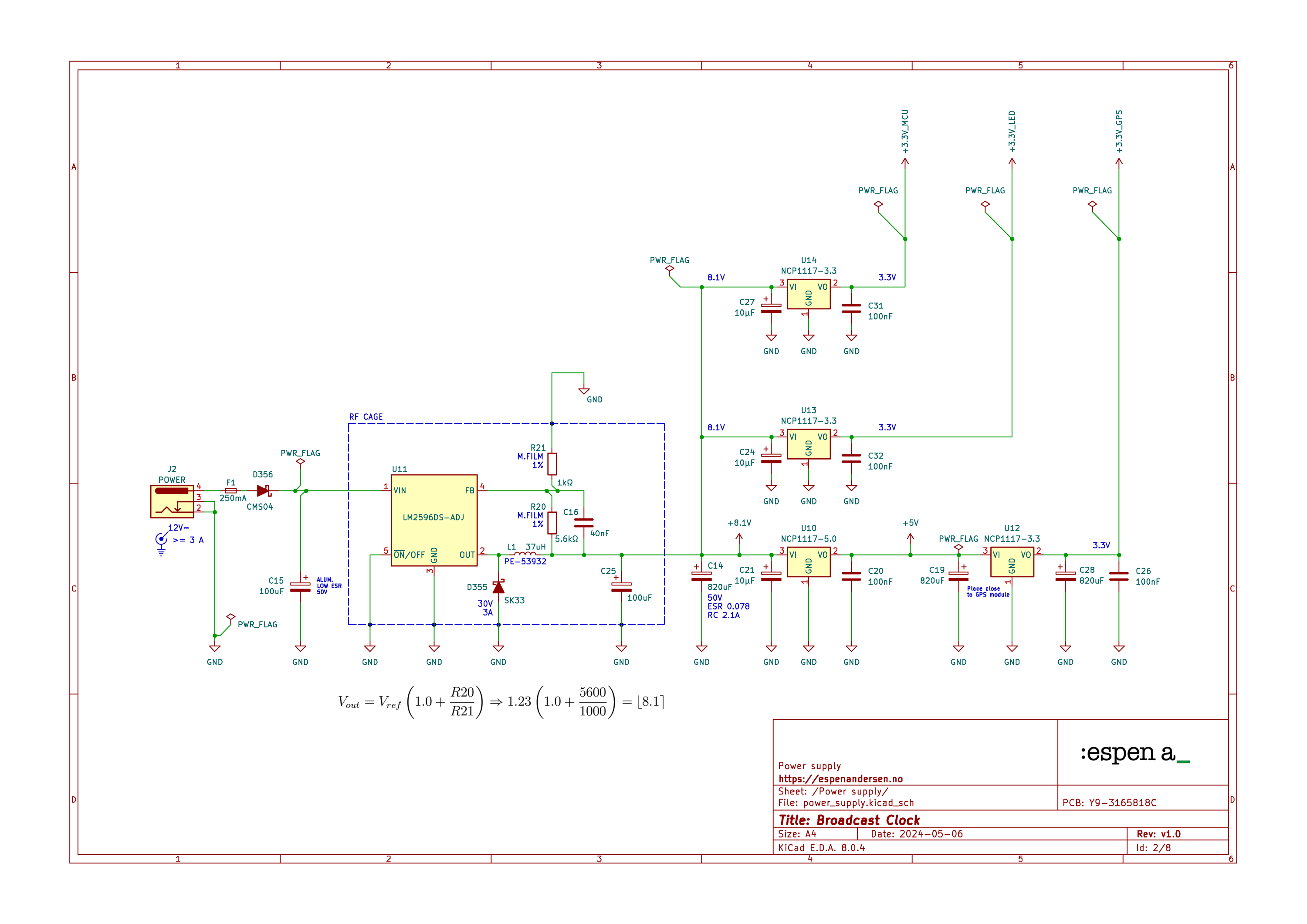
Getting rid of ripple
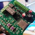
The power supply for the GPS/NTP clock consists of one primary step-down switching regulator and four linear voltage regulators.
The step-down regulator takes the input down to about 8 volts. The output is then regulated to 3,3 volts by linear regulators with good ripple rejection specs.
I implemented three separate power rails: One for the MCU, one for the LEDs and drivers and one for the satellite GPS timer module.
The power for the GPS circuitry is regulated down in three steps. First by the common step-down converter, then by a 5 volt linear regulator and finally by a 3,3 volt regulator. This reduces noise and ripple to a bare minimum.
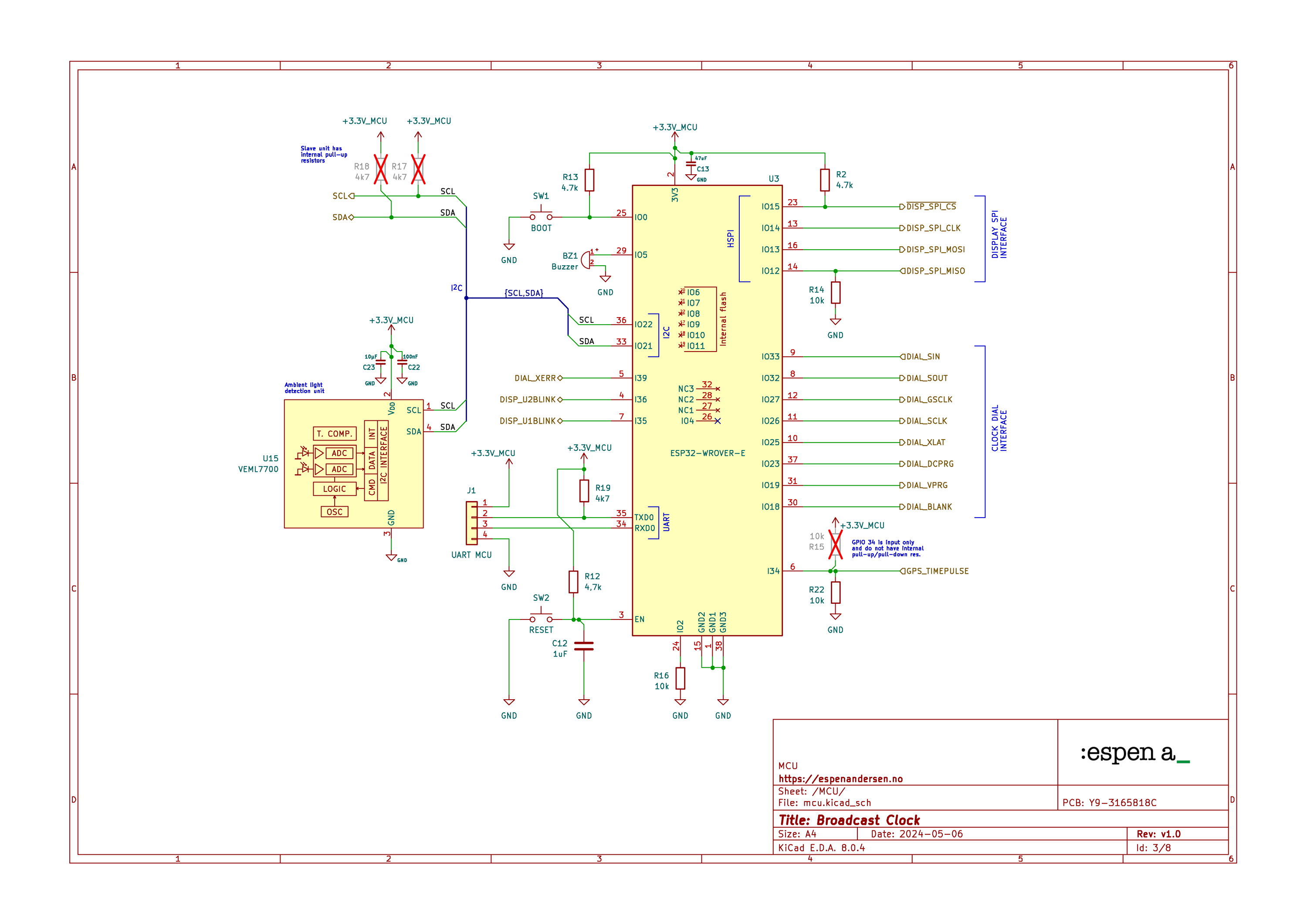
Whenever wifi connectivity is required, ESP32 WROVER-E is my favorite microcontroller module from Espressif. It is an all-in system on chip with plenty of I/O pins, and an incredible amount of ready-to-go peripherals. Even the NTP client is readily available out-of-the-box. Most of my latest electronics projects use this module.
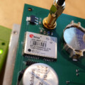
The u-blox LEA-M8T GPS module
We live in a world of wonders, and the Swiss manufacturer u-blox is behind some of the coolest system-on-chips I know of.
The LEA-M8T is a GNSS timing module capable of receiving atomic clock time from a range of different satellite navigation systems around the globe. If the receiving conditions are good, this module will give you an accuracy within just a few nanoseconds, which is mindblowing when yoou compare it to NTP.
The module communicates over varioius interfaces, the latest version also do I2C, which is very convenient as we’ve already employed an I2C bus for the ambient light sensor.
Driving the LEDs
Driving 354 LEDs is not something you would think of doing directly from the microcontroller. Even the ESP32 has too few I/O pins for that to work. So I started searching for I/O expanders or LED multiplexers that would easily connect to the ESP32.
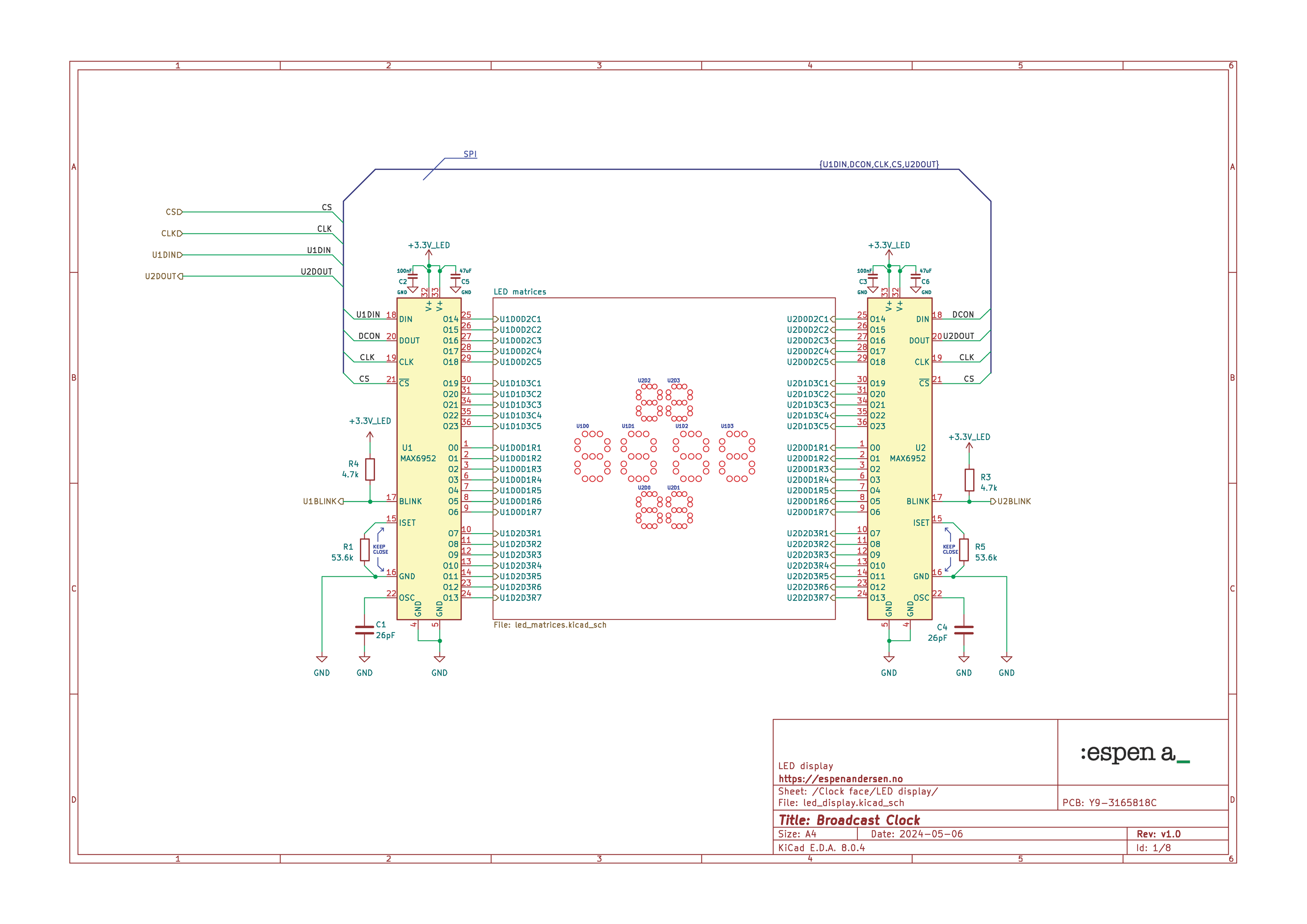
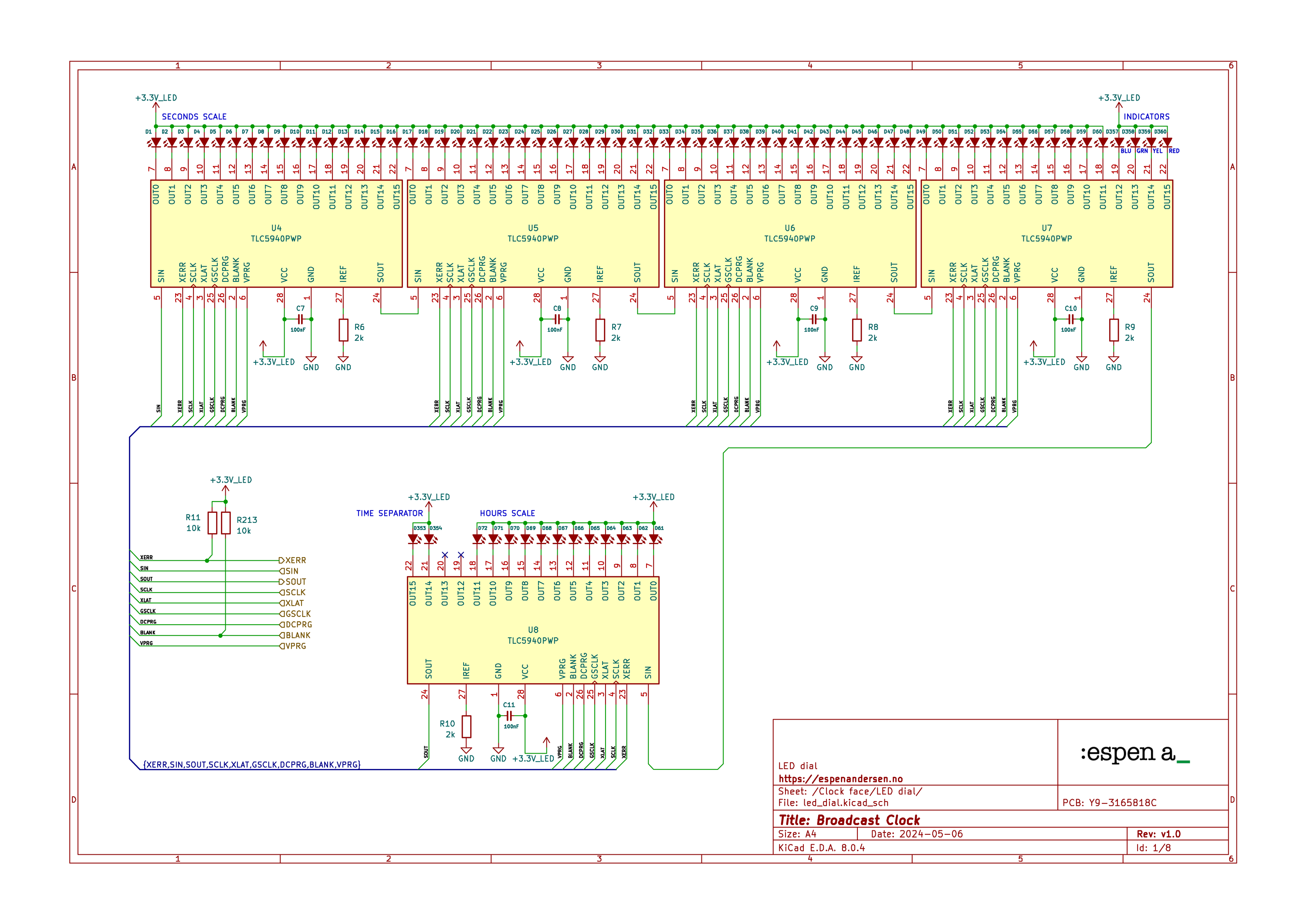
I ended up with two MAX6952 display drivers for the dot matrices and five TLC5940 LED driver for the broadcast clock’s dial. These circuits can be daisy-chained, and provides a relatively simple serial interface to the MCU.
Compared to the low price of the ESP32 module, MAX6952 is very expensive, still worth the investment. It takes care of literally everything concerning the alphanumeric displays.
MAX6952 offers a simple, 4 wire SPI-compatible interface for everything. This circut comes with its own 140 character ASCII font, but still gives you the option to generate up to 24 custom symbols. It lets you adjust LED brightness in 16 steps, and handles PWM and multiplexing completely in-circuit.
Driving the clock dial
Programming against the TLC5940 is a bit more demanding. It is a fairly simple 16 channel LED driver with a serial interface. Each channel has a greyscale register that can regulate the individual LED’s brightness in 4096 steps (!).
However, the ESP32 is responsible for the refresh routine, including the generation of the clock signal for the PWM. So, if the ESP32 lags, the LEDs around the dial will flicker. Thus, I had to take care to ensure that the dial will not suffer visually from blocking or internal context swapping.
The ESP32 is fully capable of handling this task, but the FreeRTOS operating system must assign it a higher priority. Be sensible with resource management. If you hold on to the resources for too long, you will get into a beef with the watchdog timer.
I also added a VEML7700 ambient light sensor to the project, to get automatic brightness adjustment as well.
PCB design considerations
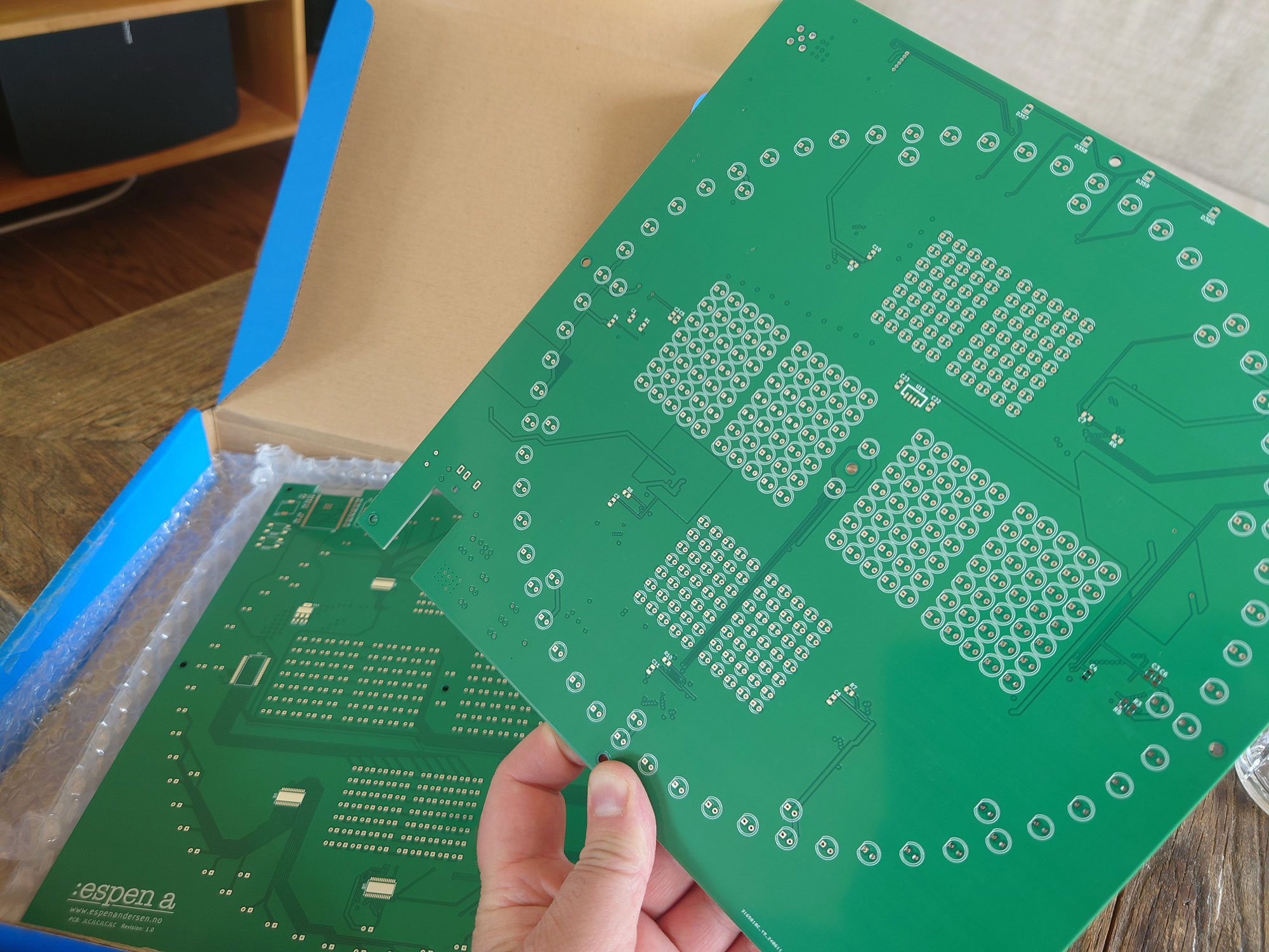
I took some time to route the PCB, but it was fairly straight forward. I went for a four layer board from JLCPCB. A board size of 239×239 mm ensured that space was hardly any issue.
The decision to use five 16-channel LED drivers for the dial instead of a pair of the larger 48-channel counterpart TLC5955 probably made the routing even easier, with fewer long traces and less via stiching.
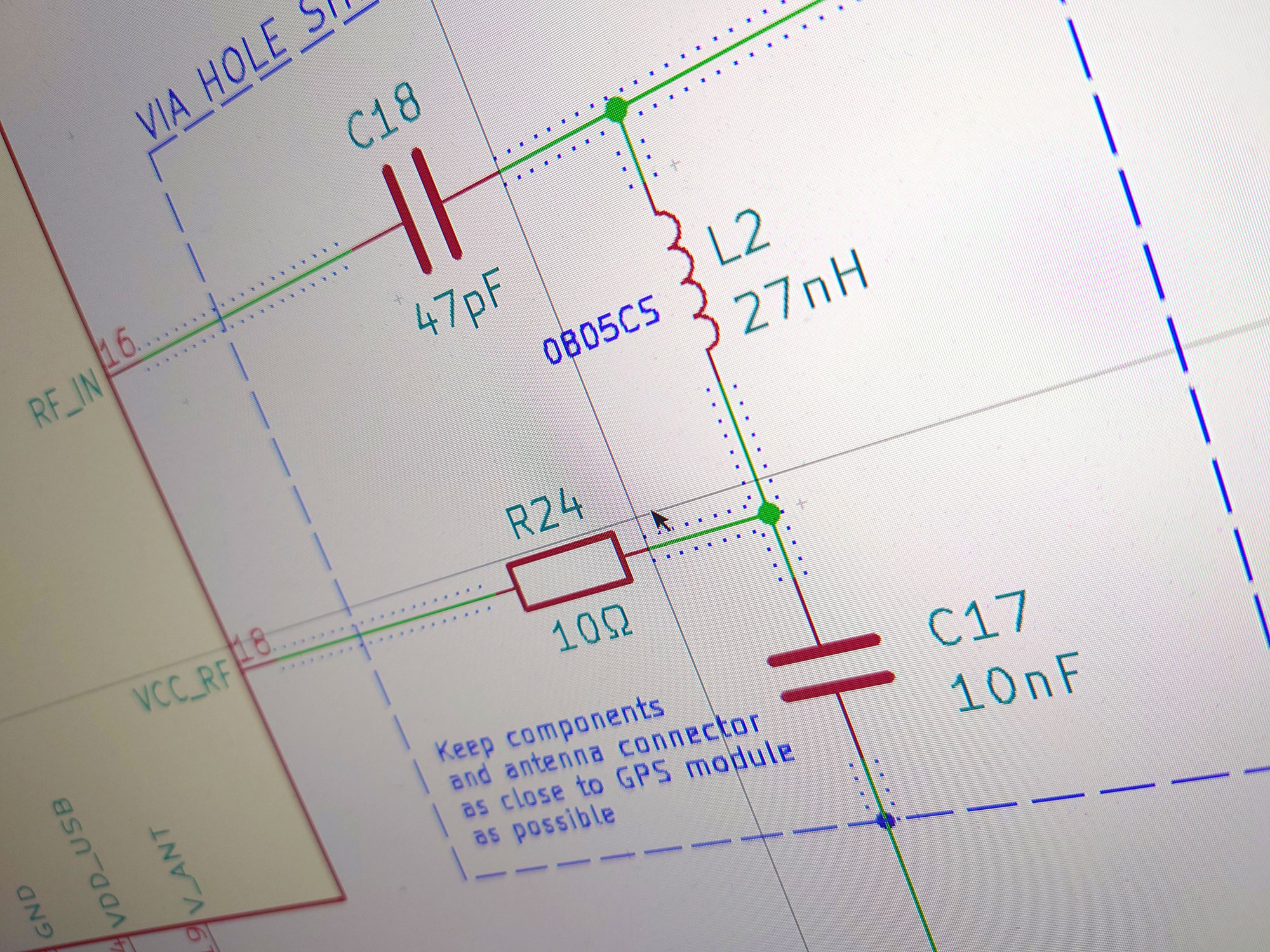
I had to pay special attention to the RF section for the u-blox module. The data sheet outlined the design guidelines to follow when routing the antenna circuitry. In short, proper shielding is crucial.
The same goes for the step-down converter. It should be placed as far away as possible from noise-sensitive circuitry.
Hence, the PSU went on the opposite edge from the ESP32 that does NTP communication over WiFi, and the u-blox satellite receiver. I spared no expenses on the filter capacitors and the power inductor, strictly following the recommendations from the vendor of the LM2596 buck converter circuit.
Visualizing the clock
KiCAD’s capability for generating 3D images from your design is very helpful when planning how to fit the various parts of your electronics project together.
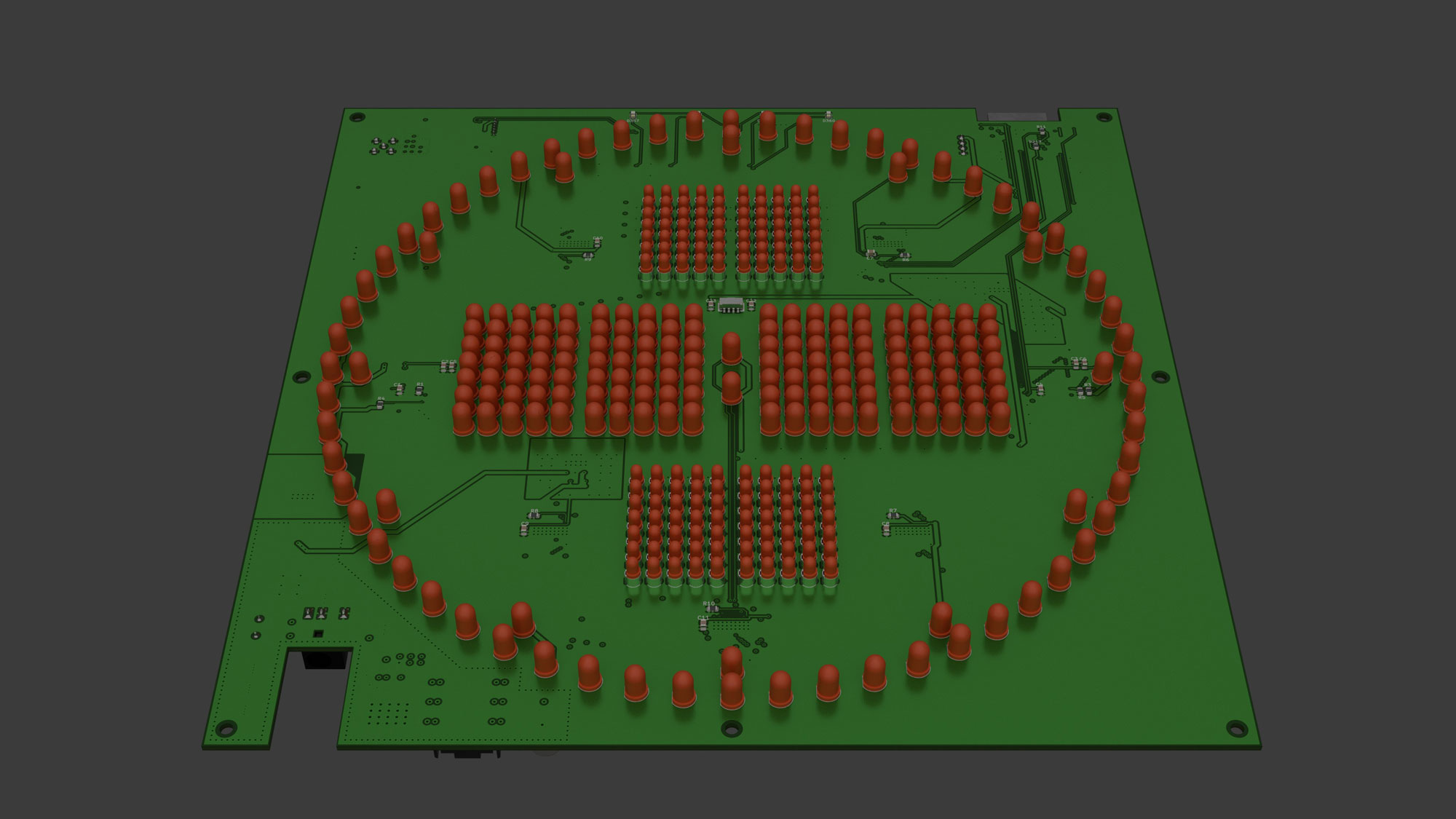
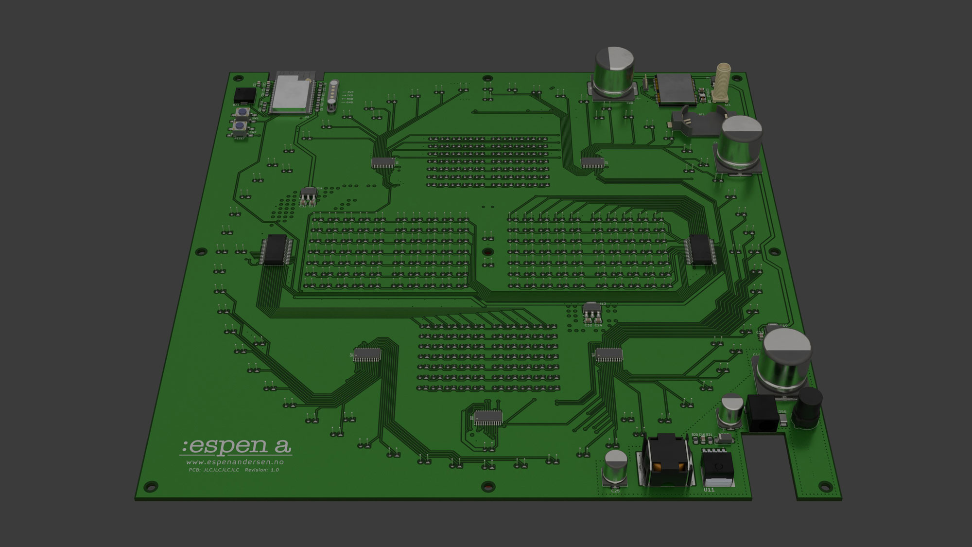
You’ll see early how things work out in real life, prior to sending the board to production. Few things are more frustrating than to discover mishaps and errors after having received your boards from the manufacturer.
So I always generate 3D images from my work. Sometimes that means actually generating models of parts not present in KiCAD’s database, but I’ve learned enough of FreeCAD to create simple 3D models.
Most of my 3D work is published on GitHub, and STEP or WRML versions may be downloaded directly from my GrabCAD account.
Soldering the LEDs
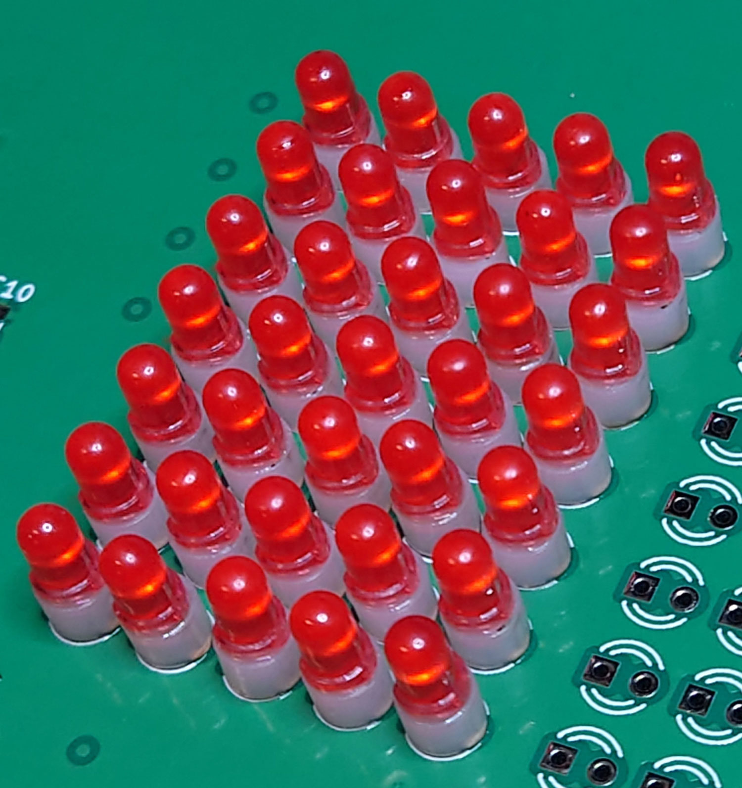
Time to assemble the electronics project and start programming it. I started by soldering the LEDs. Each of the smaller LEDs was mounted on a smal standoff, leveling them with the larger 5mm ones.
Time to assemble the electronics project and start programming it. I started by soldering the LEDs.
Each of the smaller LEDs was mounted on 3mm spacers, leveling them with the larger 5mm diodes.
I didn’t want to bend the pins on the LEDs to lock the diodes in place before soldering. Firstly, it could damage the diode. Secondly, it would increase the risk of ripping up the PCB traces when desoldering.
Here’s a little trick to hold the diodes in place while soldering: When flipping the PCB over for soldering, put a small foam pad under the diodes. By applying a bit of pressure to the board, the LED’s will be pushed firmly in place.
Testing the power supply
After doing the LEDs, I continued with the power supply section. Before soldering pricy circuits like the dot matrix LED driver or the u-blox satellite module, it’s wise to verify that all the other parts of the broadcast clock circuitry works according to plan.
The first stage of the power supply is the LM2596-based step-down buck converter. It can be configured to deliver a range of different voltages, depending on an external reference resistor. According to my calculations, it should output about 8.1 volts.
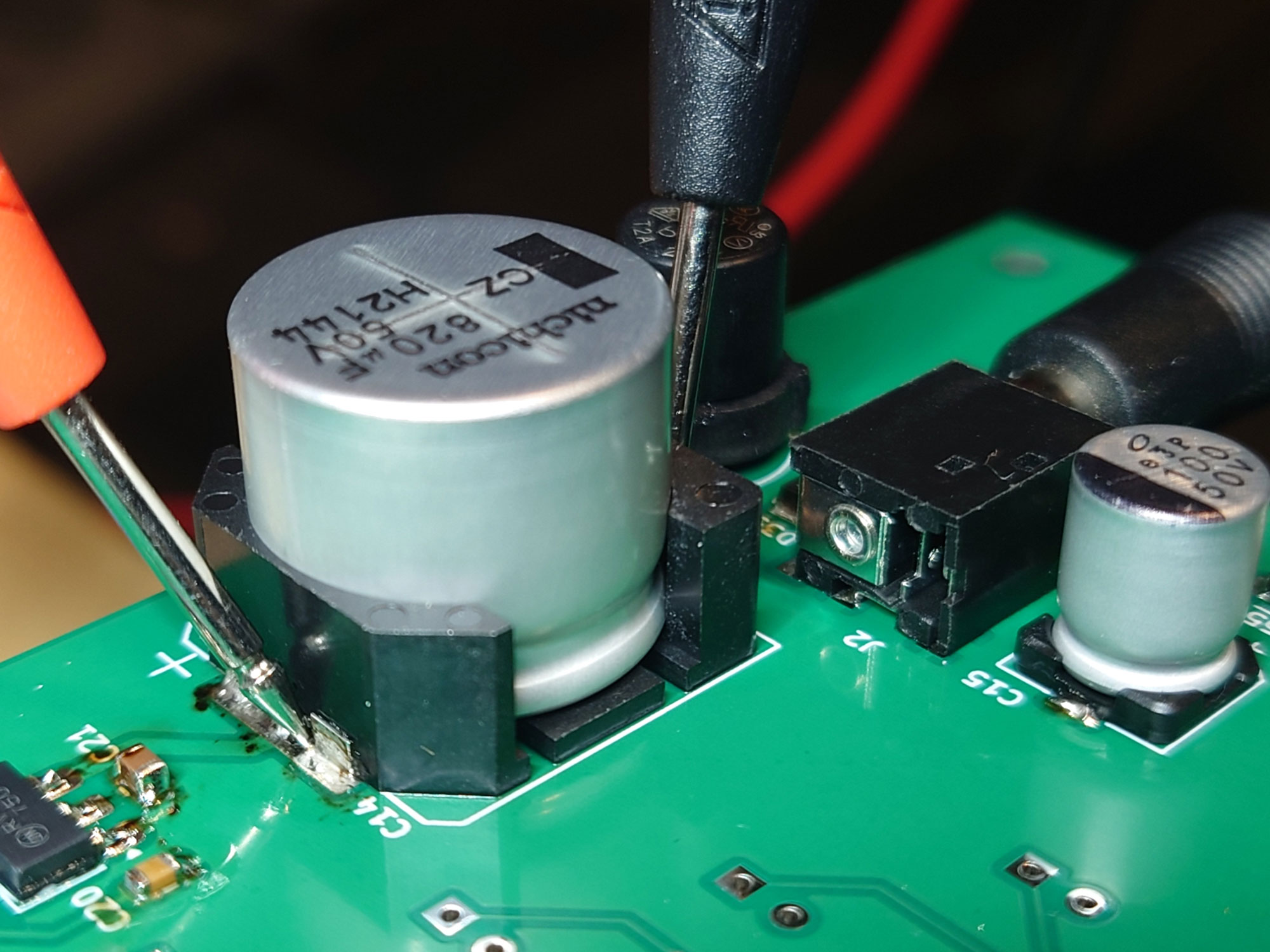
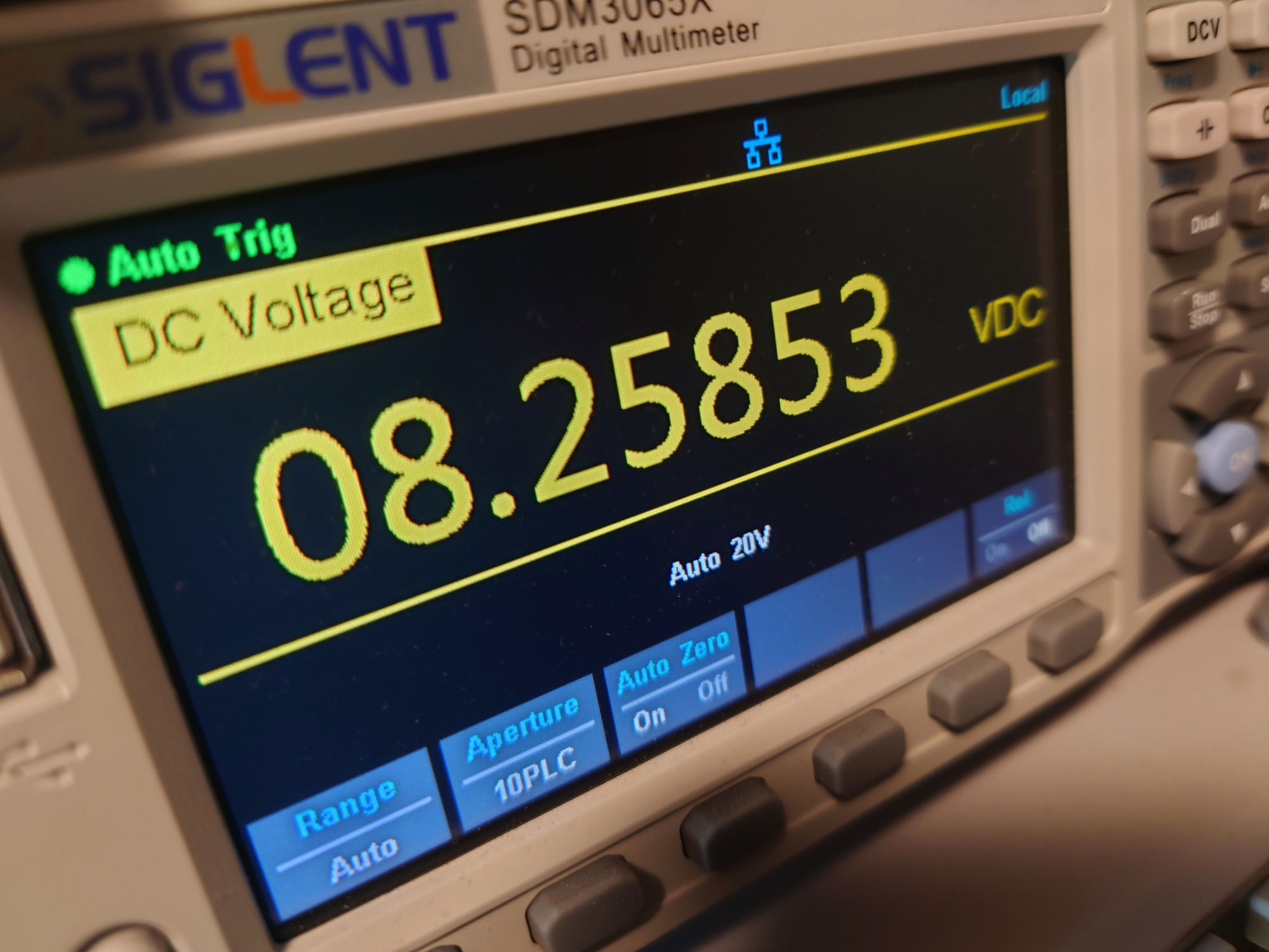
Measuring the voltage from the buck converter showed a voltage of 8.26 volts unloaded, which is good. Once I started loading the supply, the voltage dropped to almost exactly 8.1 volts, as anticipated.
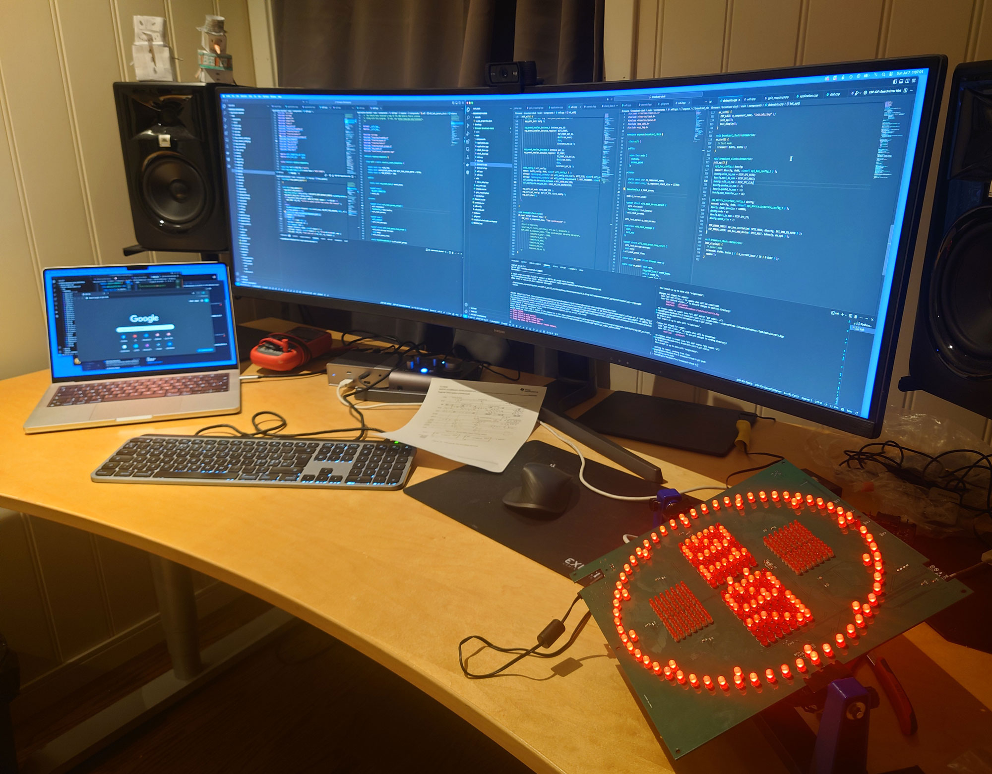
Programming the ESP32
Even something as mundane as a wall clock requires stunning amounts of code to work properly. Not to mention all the extras I put in to this project. DNS spoofing, NTP client, web server, u-blox receiver, wifi control, display drivers, ambient light sensor and so on.
I prefer to use Espressif’s IoT Development Framework (IDF), which is written in C. You can then code your own application in C or C++ (or more commonly for me, a nasty combination of both).
Espressif’s GitHub repository is full of coding examples, and there’s a large community waiting to help you out when problems arise.
You may instead consider using the Ardino c++ core for programming ESP32. It leverages the native C API from Espressif, eliminating some of the need for drilling down on raw pointers and complicated data structures.
It provides a fairly large library of C++ classes for you to use, abstracting you from the nitty gritty stuff. Implementing NTP, for example, is a breeze.
There’s also an option of using MicroPython for programming the ESP32. But it introduces more overhead.
The final clock
I admit it doesn’t exactly blend in when hanging on my living room wall. But it should fit well in a home office, in a podcast studio or in a reception area.
You don’t even have to put it on the wall. The clock will stand firmly on the shelf on its own.
The above video shows some of the functionality. You can use your pone or PC to access the web configurator to adjust the clock’s settings. There you can configure the following clock preferences:
- Time zone
- NTP server
- WiFi connection
- Whether the dial should count up or down
- Automatic or manual display brightness
- 12 or 24 hour clock
I will update the post as soon as I get the GPS module. Getting the M8T chip across the border turned out to be a bit of a hassle, due to a strict export control regime. I had to fill out a form explaining what I’m going to use it for. But it’s on its way.

Hi Espen,
This is really a great prosjekt and I hope we meet one day to discuss it further. I like ur writings too they are well crafted.
Thanks 🙂