Learning to create 3D models in FreeCAD has been a priority for me during the last couple of months. I’ve been taking on increasingly complex modeling tasks, allowing me to test out new tools and workbenches. Here’s my first attempt at using the Sheet metal workbench.
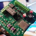
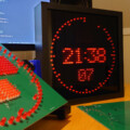
Hunting down parts for an electronics project often ends up involving 3D work. A through-hole, vertical USB connector that I recently acquired online posed a new 3D modeling challenge.
The vendor had no CAD drawings to offer. And, since I always make visualizations my boards, a proper 3D model for the connector is crucial.
The 3D models I found online were either too simplistic or differed too much from the one I got. Additionally, freely available models of USB connectors are often a bit rough, usually created with boolean operations only.
I’d rather model the shield as a real stamped-and-formed part: A flat sheet that’s bent into a rectangular sleeve, with a visible closing seam and stamped-out retention tabs that are formed (bent) outward/inward.
Unfolding the USB connector
So, one day I decided to give the sheet metal workbench a shot. Of course, it turned into a full weekend project — which, in turn, bled into the following week.
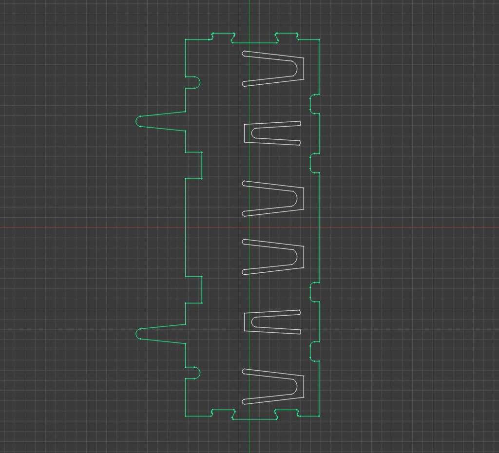
I started out making a contiguous drawing of the shield, laid flat out on a 2D plane. The vendor’s tech drawings were good enough to create an fairly accurate outline in Illustrator (or any other 2D drawing software).
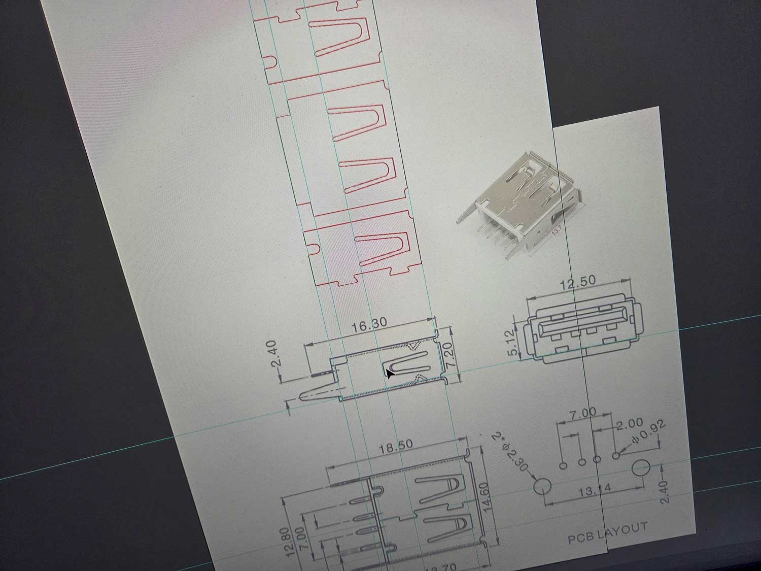
I traced each of the surfaces from the drawing, including the cutouts for the retention tabs. I split the bottom surface along the seam so that the two halves serve as start and end pieces.
The final version of the 2D drawing lends itself to a very convenient workflow. For simplicity, I exported the outline as a jpeg image and imported it directly into FreeCAD.
FreeCAD has an image import feature that lets you place a template image in the background while doing the sketch work. Just import the image and create a blank sketch.
Preparing the sheet metal
Before starting to sketch up the outline, the imported template image had to be scaled correctly.

I started by sketching a single rectangle to represent the shield in top view — centered and fully constrained to the exact dimensions.
During scaling and repositioning of the template image, I could now use the rectangle as a reference and align the template precisely before tracing the full outline.
I carved out the retention tabs by extruding the sketch containing the cutot profiles, using it for a boolean cut on the 0.3 mm padded outline.
The tabs would be bent inward at a later stage, after completing the basic shaping of the shield.
Before starting to bend the shield back into its final shape, I had to add single sketches with fold lines for the fold-a-wall tool in the sheet metal workbench.
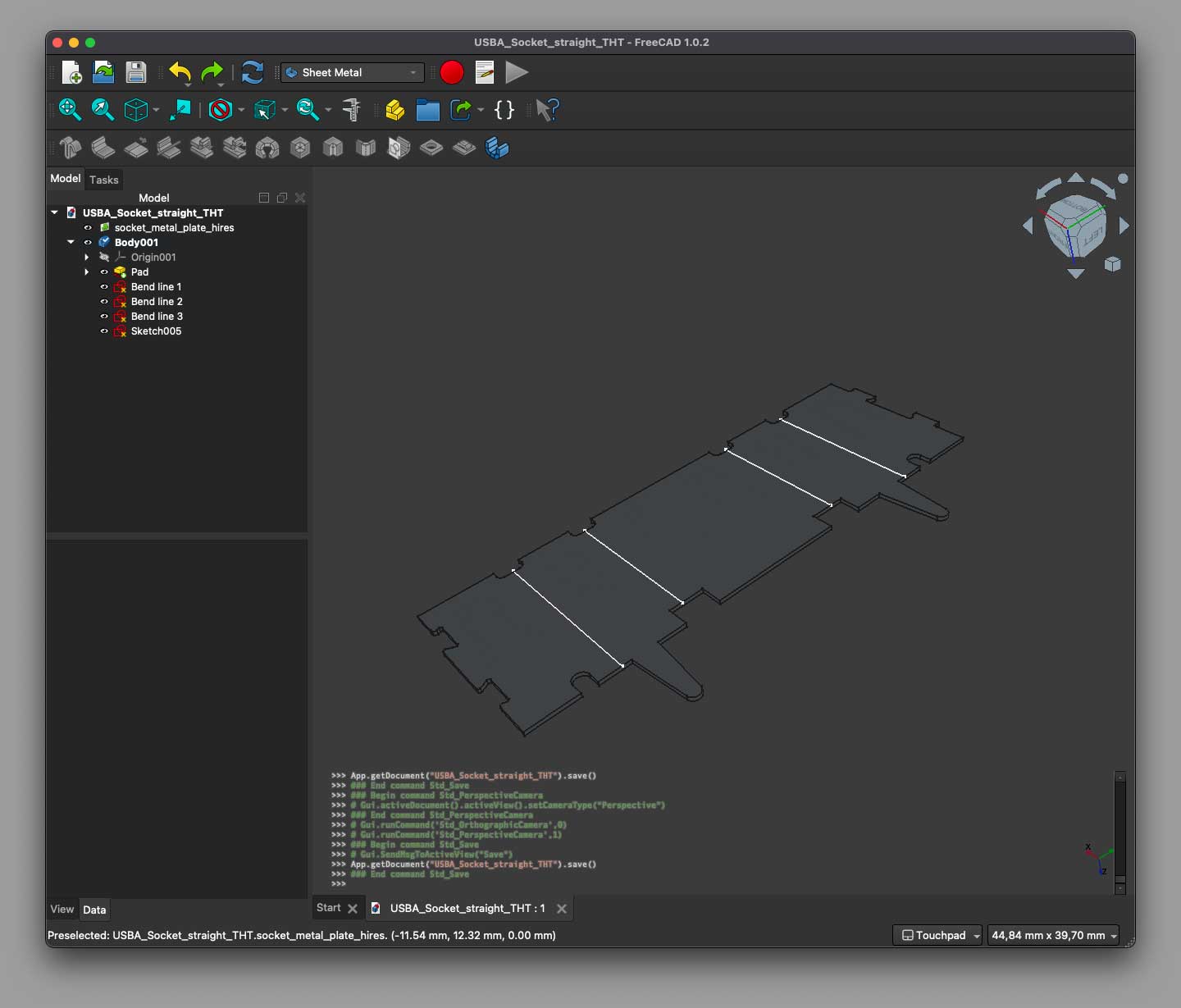
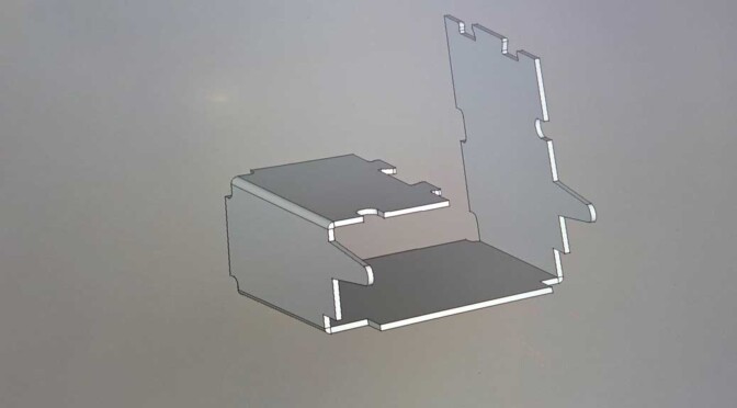
Bending it all back to shape
Finally, it’s time to go backward, folding it back into a proper USB connector shield.
As usual, most of the time consumption lies within the preparations. Doing the actual folding was done in a couple of minutes. Still, there’s a couple of caveats. Firstly: Position the fold lines at the center of the bend and fold inwards around the lines. Secondly: Set the radius sufficiently low. I went all the way down to 1µm.
Also, keep in mind that each fold operation displaces a part of the target object. When doing multiple foldings in sequence, work progressively along one direction, i.e. from left to right.
Make sure the “fixed” part of the object stays in place as you go along; otherwise the model will drift and no longer line up with the fold lines you prepared earlier.
If the wrong side starts moving, check the tool’s Flip direction check box. Just let the object wind itself up, like in the video.
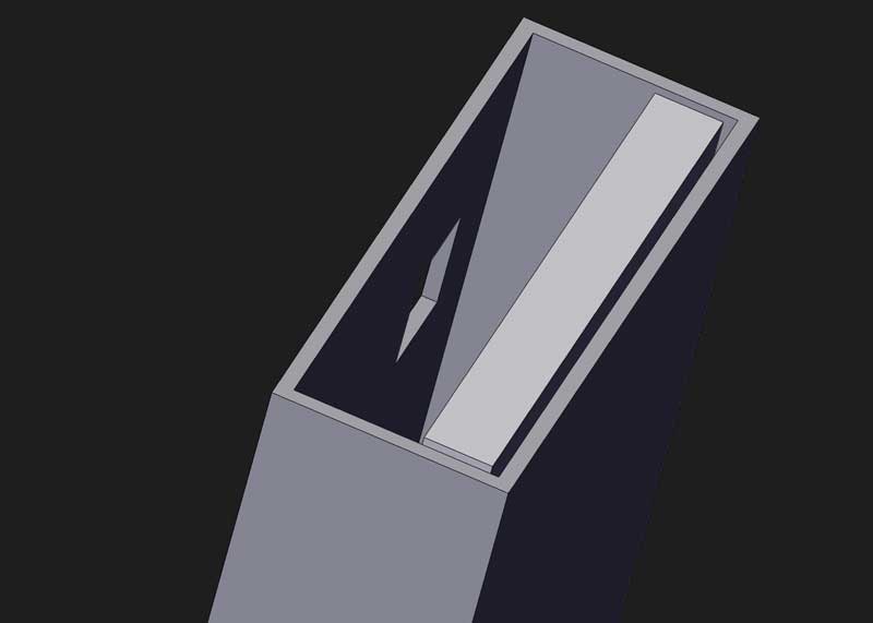
Final wrap-up
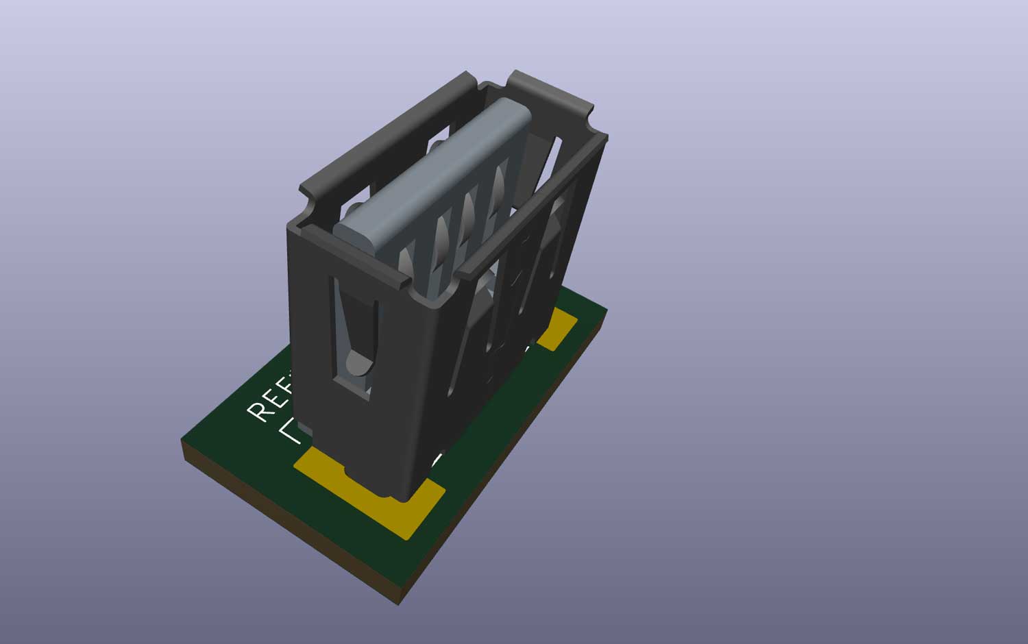
Next thing out is the retention tabs and the lead-ins at the connector front. This is kindof tedious, as you’ll have to draw the fold lines at the right position for every operation, then choosing the right angle before folding each piece one by one.
Needless to say, it was lots of trial and error before getting it right. But I still think the final result turned out to be quite decent.
I could probably have used way more convenient methods to achieve a similar result, but this project was all about a novice playing around in the Sheet metal workbench, struggling and fighting his way toward a working result.
Next time, I might discover more sophisticated tools and workflows. Feel free to drop a comment if you know of better methods.
I’ve uploaded the USB connector model to my GrabCAD profile, for anyone interested.