I guess a piece of wood cut at the correct angle would do the trick just as well as 3D-printing an angled closet rod mount. But if all you have is a 3D printer, then everything starts to look like a 3D modeling job…
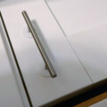
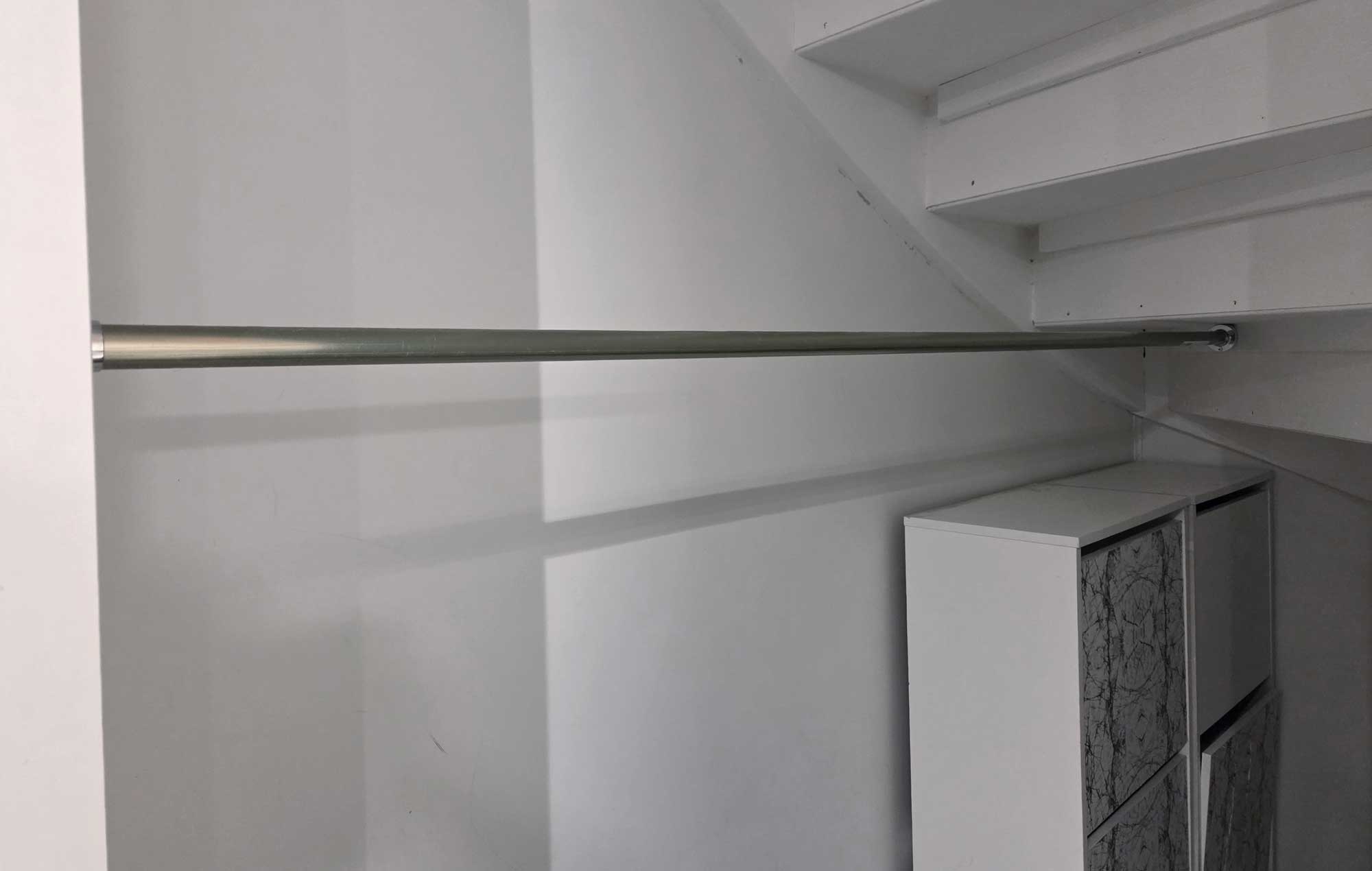
I was given the task of putting up a closet rod for a wardrobe beneath a staircase (I’m easy to persuade for a dinner). The rod had to be mounted between a shelf wall and the back side of one of the stair’s steps.
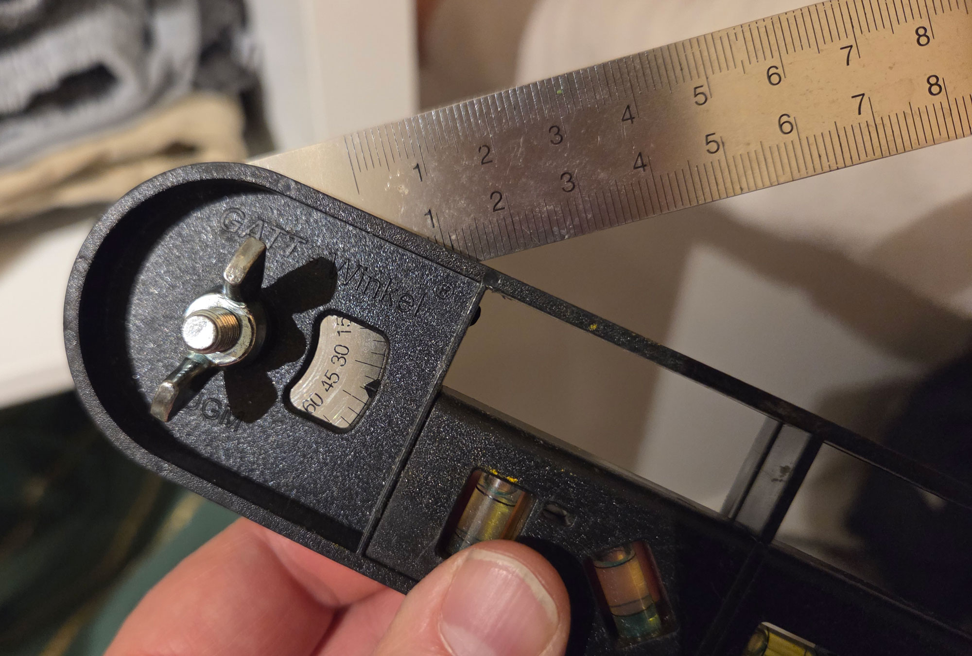
The challenge
Unfortunately, the step was angled at about 50 degrees, hence not at all perpendicular to the rod.
So I needed some kind of angled mounting adapter to align the rod collars. I happily went to work with QCAD and FreeCAD.
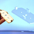
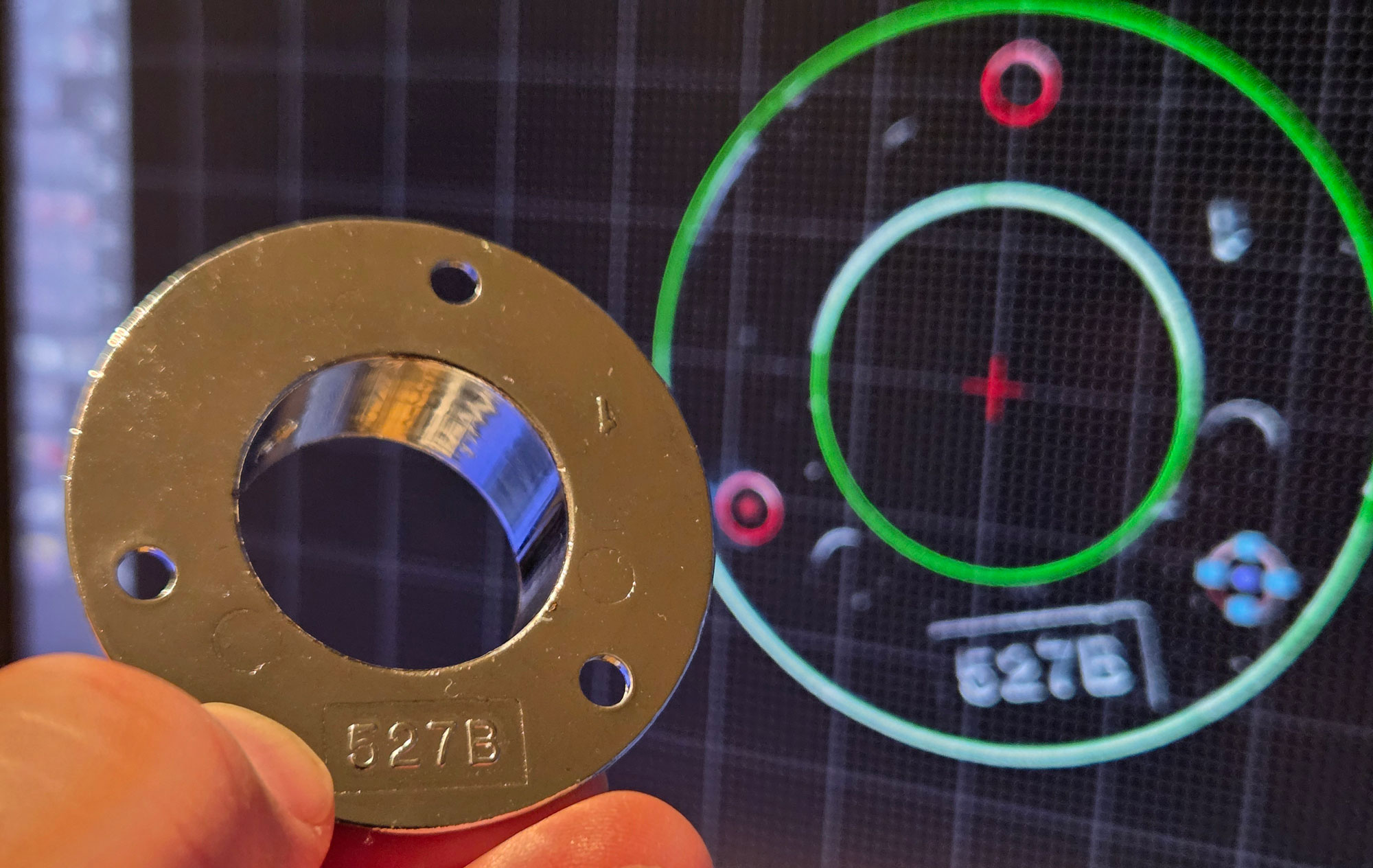
First off, I needed a scan of the mounting collar, following the technique I described in a previous post about accurate 3D modeling with a flatbed scanner.
Starting with 2D
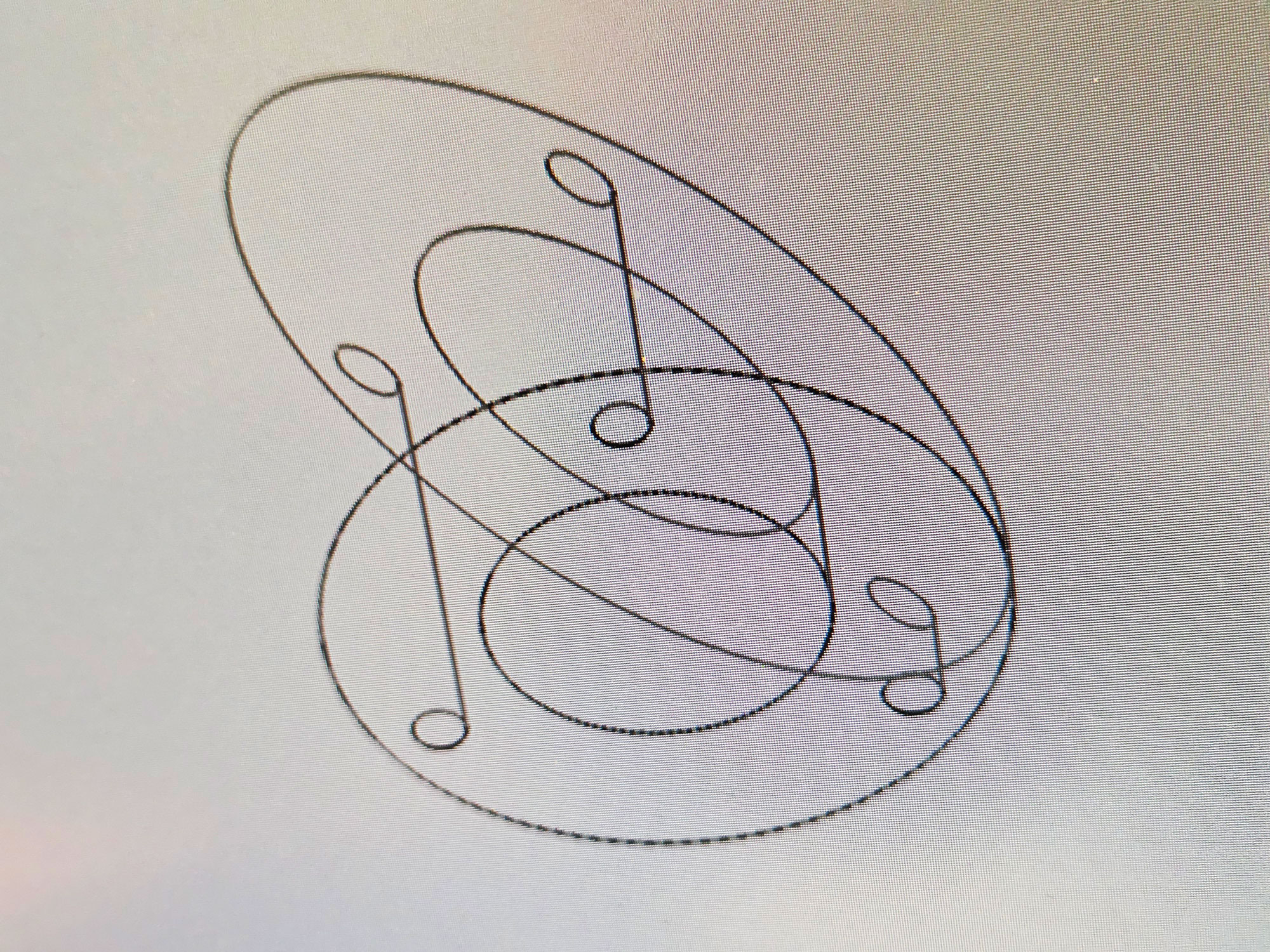
I imported the scanned image into QCAD, my favorite 2D tech draw program. I then made a DXF file of the footprint of the collar, positioning the mounting holes exactly right.
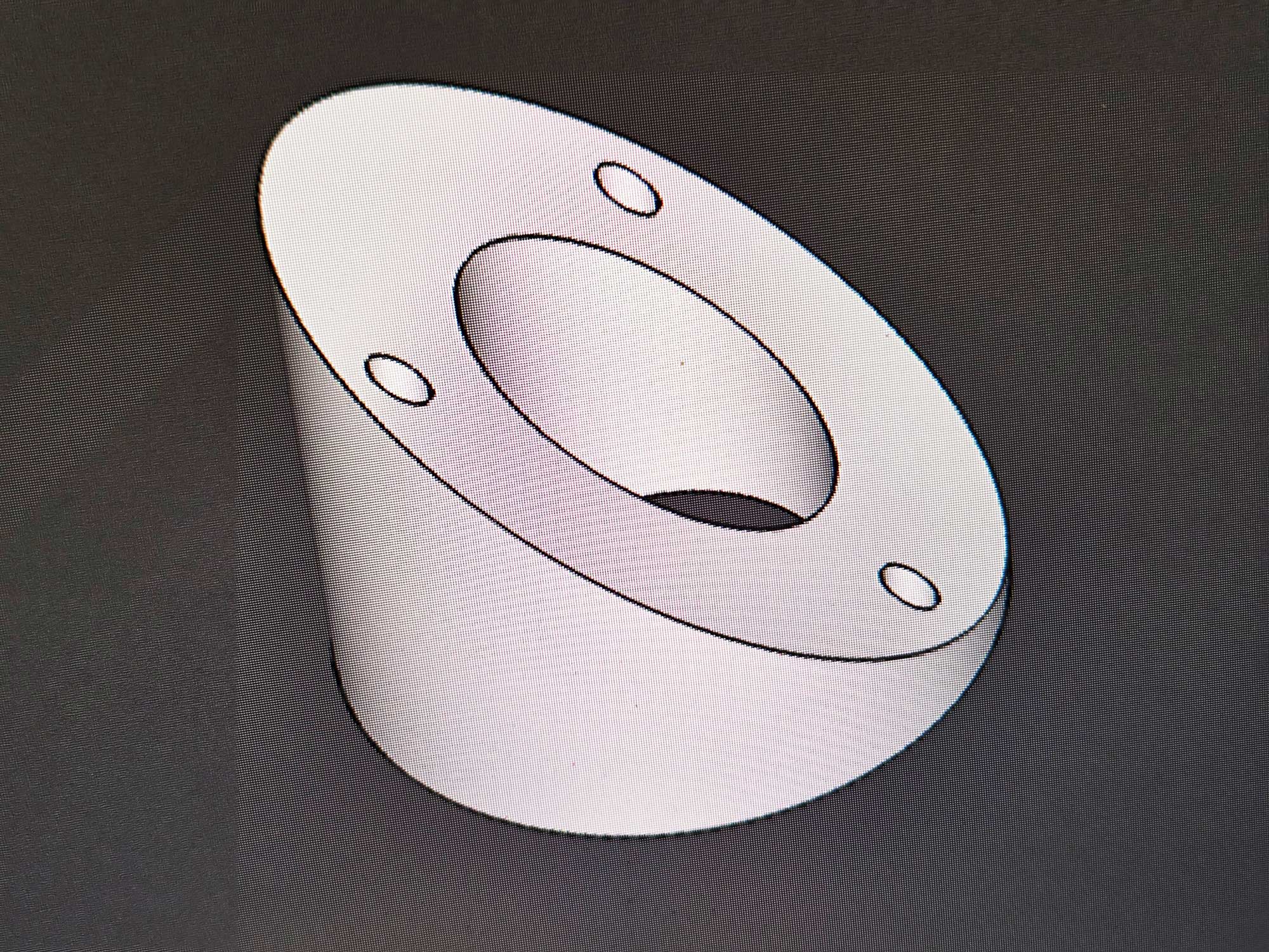
Importing the DXF outline in FreeCAD is easy. After that, I could create a sketch from it, extrude the sketch and cut out the mounting holes. I then cut it to angle by using boolean subtract with a properly positioned and rotated tool object.
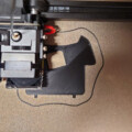
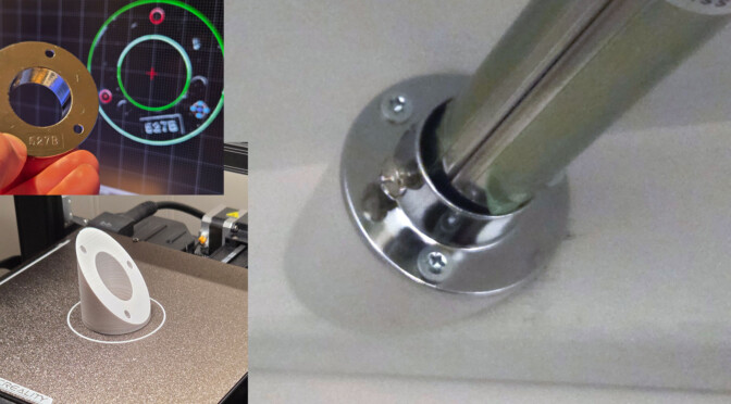
The adapter came out great on my Creality Ender-3 S1 Pro, using PETG filament.
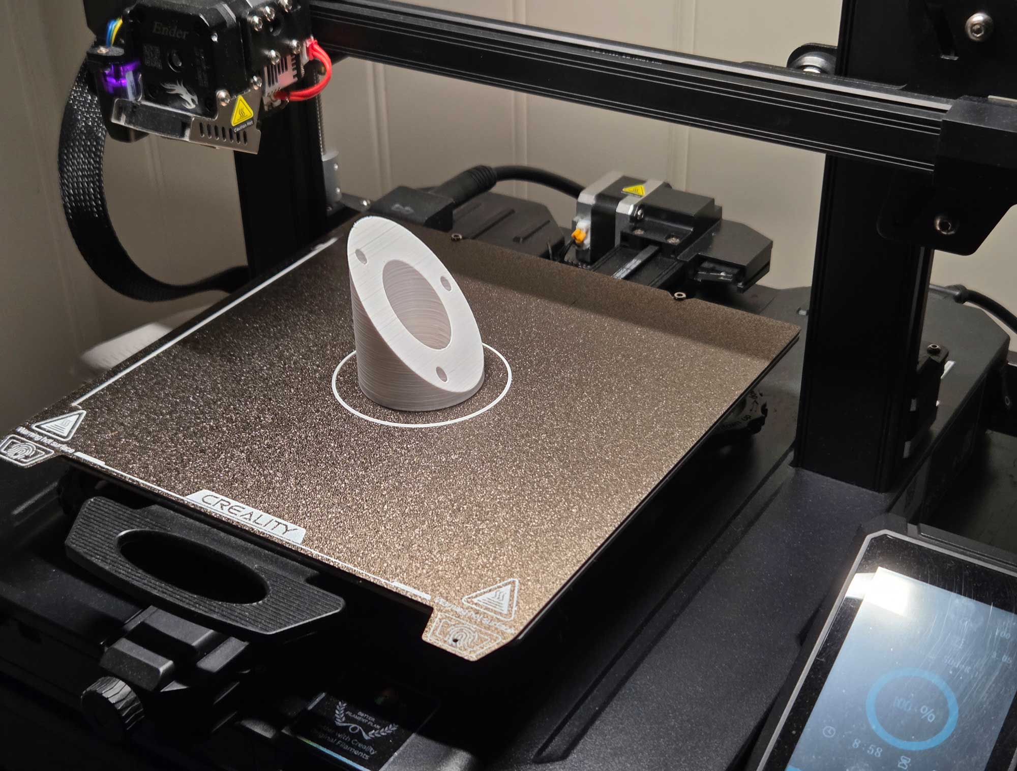
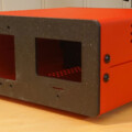
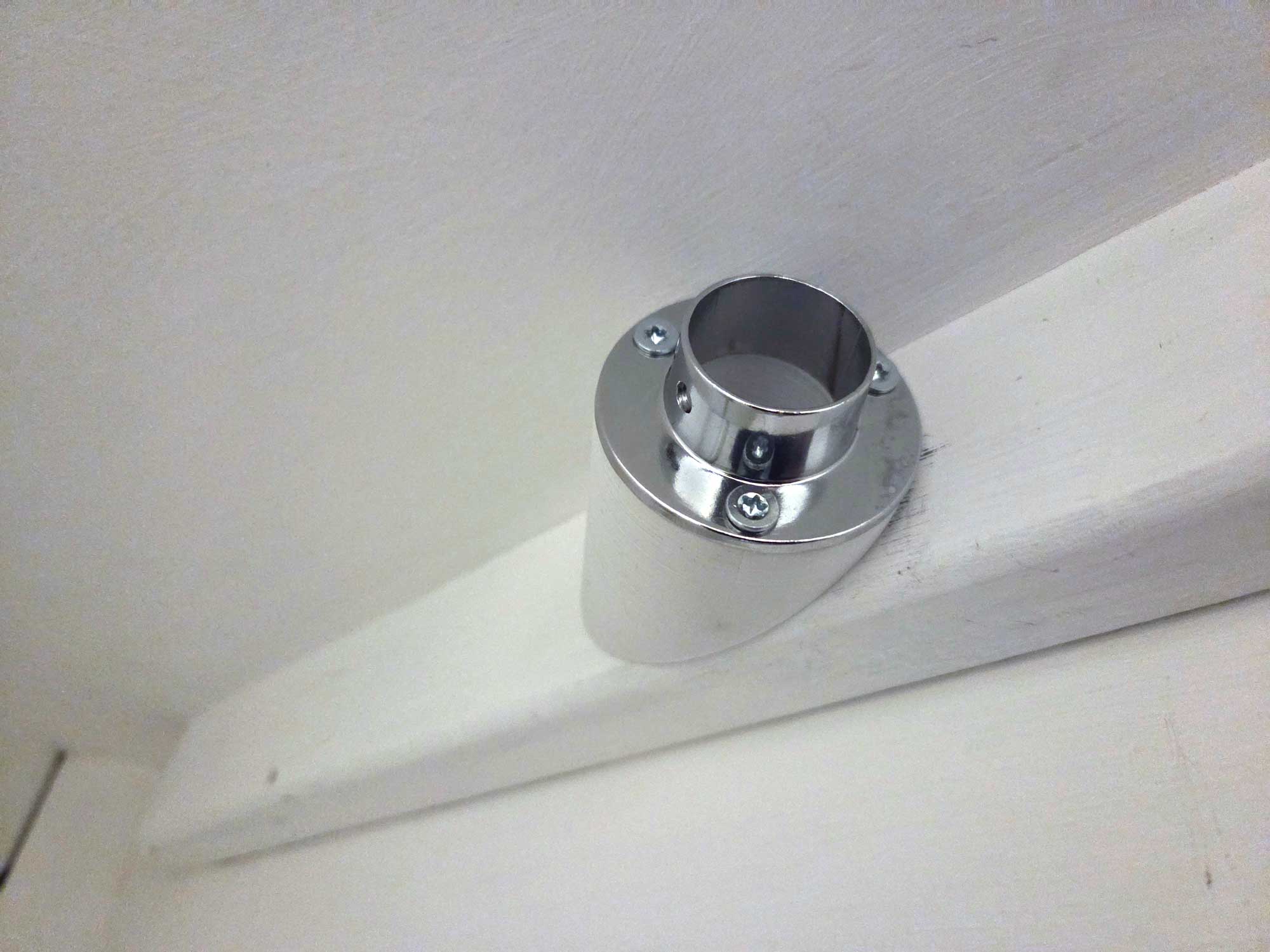
The result
I had a hard time finding 4mm screws long enough to peek through the deepest part of the model. Eventually, I found a box of 4×70 mm wood screws that did the job just fine.
I have uploaded the 3D model, including the FreeCAD and QCAD files to my profile at GrabCAD. You’ll need the FreeCAD file to alter the angle.