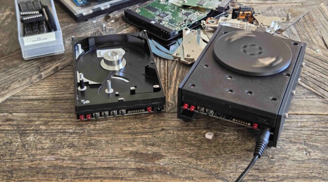
Crashed hard drives don’t have to end their days on the dumpster. Here’s my way of re-purposing any hard drive with a high-end spindle motor as a slide ringing table.
I recently got into amateur microscopy, and the old techniques for making prepared slides is among the things that really inspires me. The fact that there are almost fully intact, centuries old microscopy slides in museums, intrigued me to the point where I started making my own prepared slides.
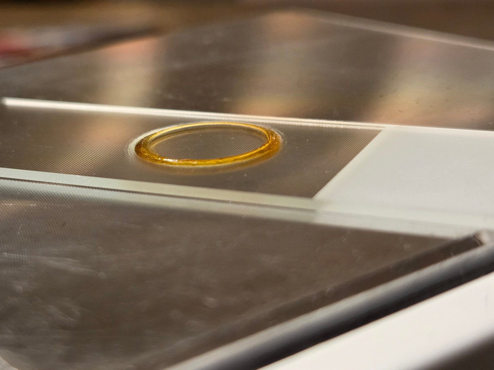
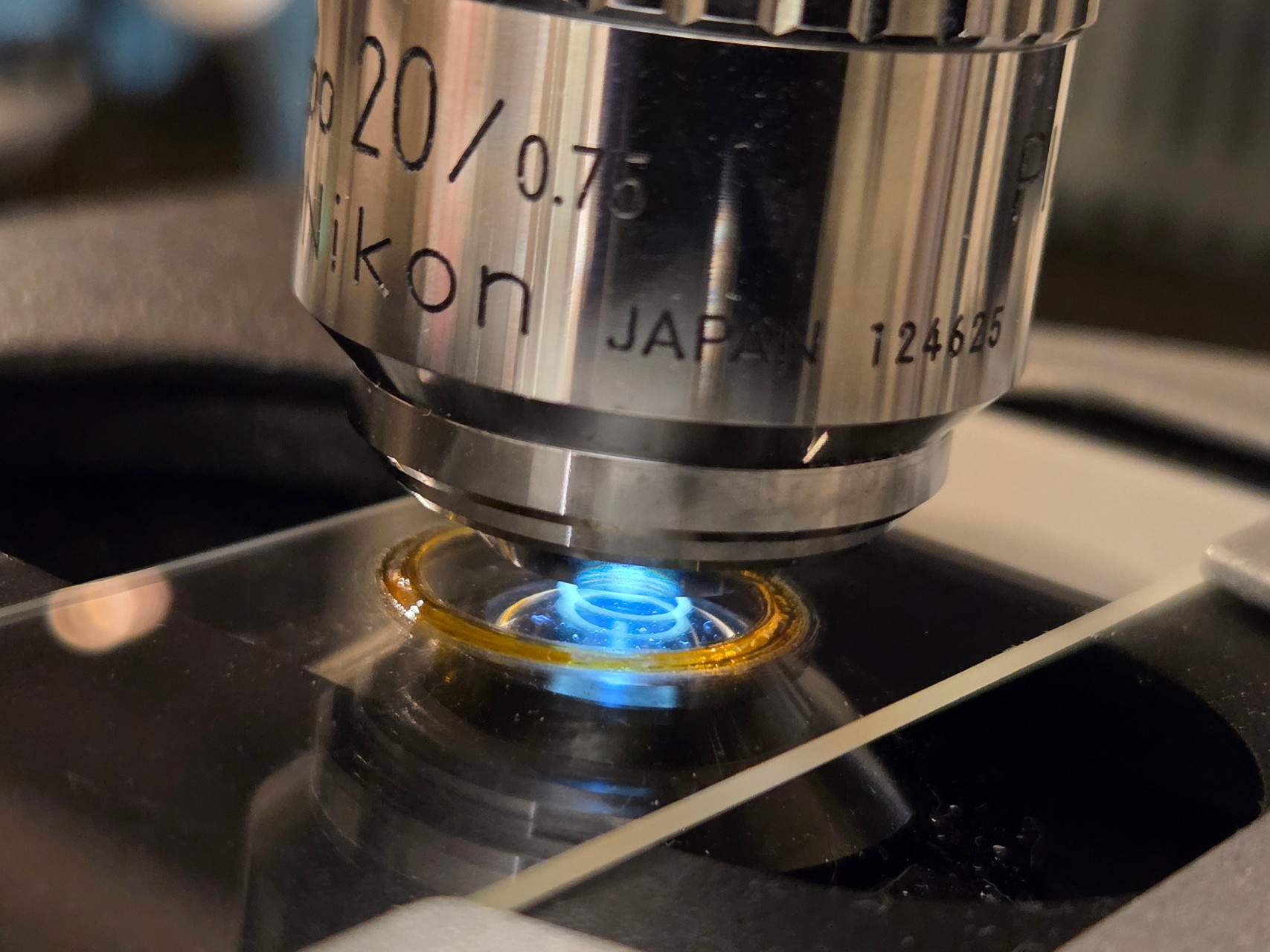
A proper ringing table
The concept of using a so-called ringing table to apply a good looking ring of sealing varnish around the edge of the cover slip, had me look around my home for remedies that could work as such.
To anyone that knows me, it comes as no surprise that this quickly evolved into another electronics project.
Hitting the spindle
Like many computer nerds, I’ve got a bunch of old hard drives lying around. Some with bad sectors, some too small to be of much interest and others again being just too old to be trusted with new data. But they all have one thing in common: A nice, fully functional, state-of-the-art spindle motor.
I selected a twenty year old drive from Western Digital as target for my rebuild. I gutted it completely, keeping in place only the spindle motor.
Assuming these motors could work quite well as microscopy slide ringers, I started looking for specifications and driver chips.
Taming the monster
A HDD normally operates at speeds that would be outright dangerous if not contained. For my idea to work out, there had to be a way to bring the motor speed down to a much safer range than breakneck 7200 rpm.
Besides that, the torque should be low, so no one get hurt touching the rotating table by accident.
I trusted DRV10983SQ from Texas Instruments to do the job. Most hard drive spindle motors have three coils connected in a star configuration (three-phase), and the DRV10983 series is exactly for this motor variant.
The driver chip is sensor-less. It uses phase currents and back EMF voltages to detect a range of fault conditions. Hence, it’s easy to program the MCU to halt the motor immediately, if someone, for example, stops the rotating table by hand.
Slide ringer runaway
There’s also this: When driving a spindle motor at very low speed/current operating points, you risk a runaway condition, where the motor unexpectedly starts accelerating towards full speed. Not a good trait for a ringing table. This can happen when back-EMF voltages become too small for reliable detection by the driver’s control loop.
To counter slide ringer runaways, I programmed the microcontroller to continuously monitor the driver’s FG output pin.
When configured appropriately, the driver produces one FG pulse per revolution. Whenever the pulse rate exceeeds a predefined threshold, the MCU immediately shuts down the motor.
The driver chip even provides 3v3 regulated power to the MCU, so no extra voltage regulator was required. Bear in mind that to utilize the power output for the MCU, you must aquire the SQ version of the chip. It keeps the 3v3 rail energized in standby mode, even when the motor is not running.
Going easy on MCU
A motor driver doesn’t need a powerful system-on-chip like an ESP32 module to work well as a slide ringer. So I grabbed a PIC24F04KA201 microcontroller I had stocked up while working on another project.
This controller has what it takes for the task. It runs at 32 MHz with an external oscillator, can communicate with the motor driver over i2c, and has an external clockable timer (counter) that is perfect for capturing the output pulses from the FG pin.
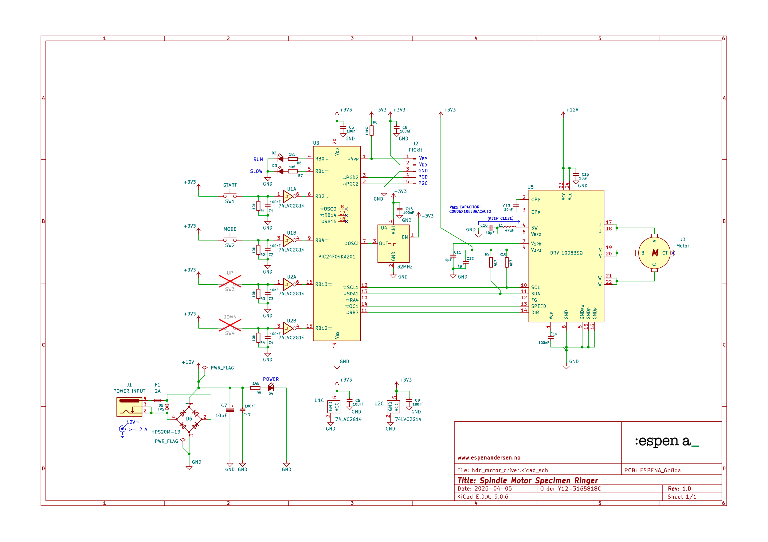
This chip, however, has only 4K of program memory, so you can’t just hack away. You’ll hit the 4K limit before you know it if you don’t take care in writing your code sparingly. You might consider 24F08KA101 for 8K program memory.
One great advantage of PIC is low power consumption. That means that the rather limited 3v3 output from the DRV10983 won’t get overloaded.
Controlling the controller
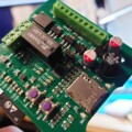
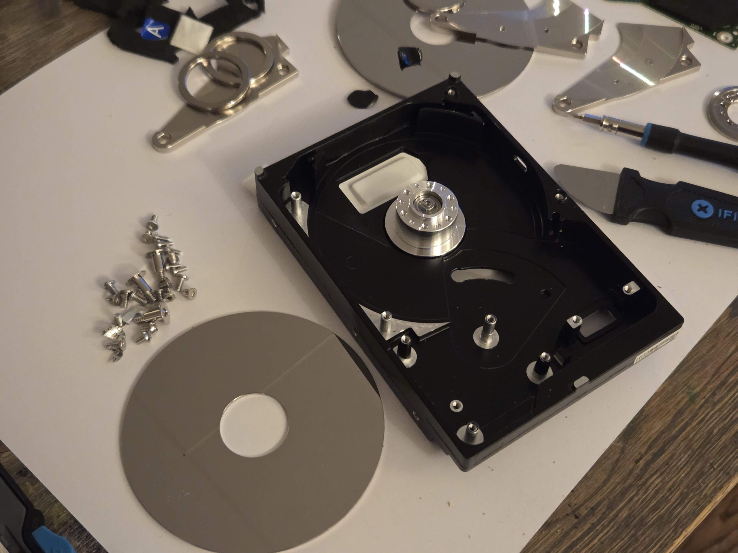
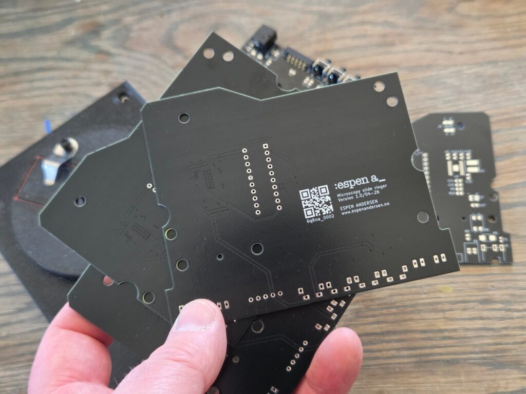
Hard drives are built rock solid, and are oftentimes repair-friendly. The disk controller board can usually just be removed directly.
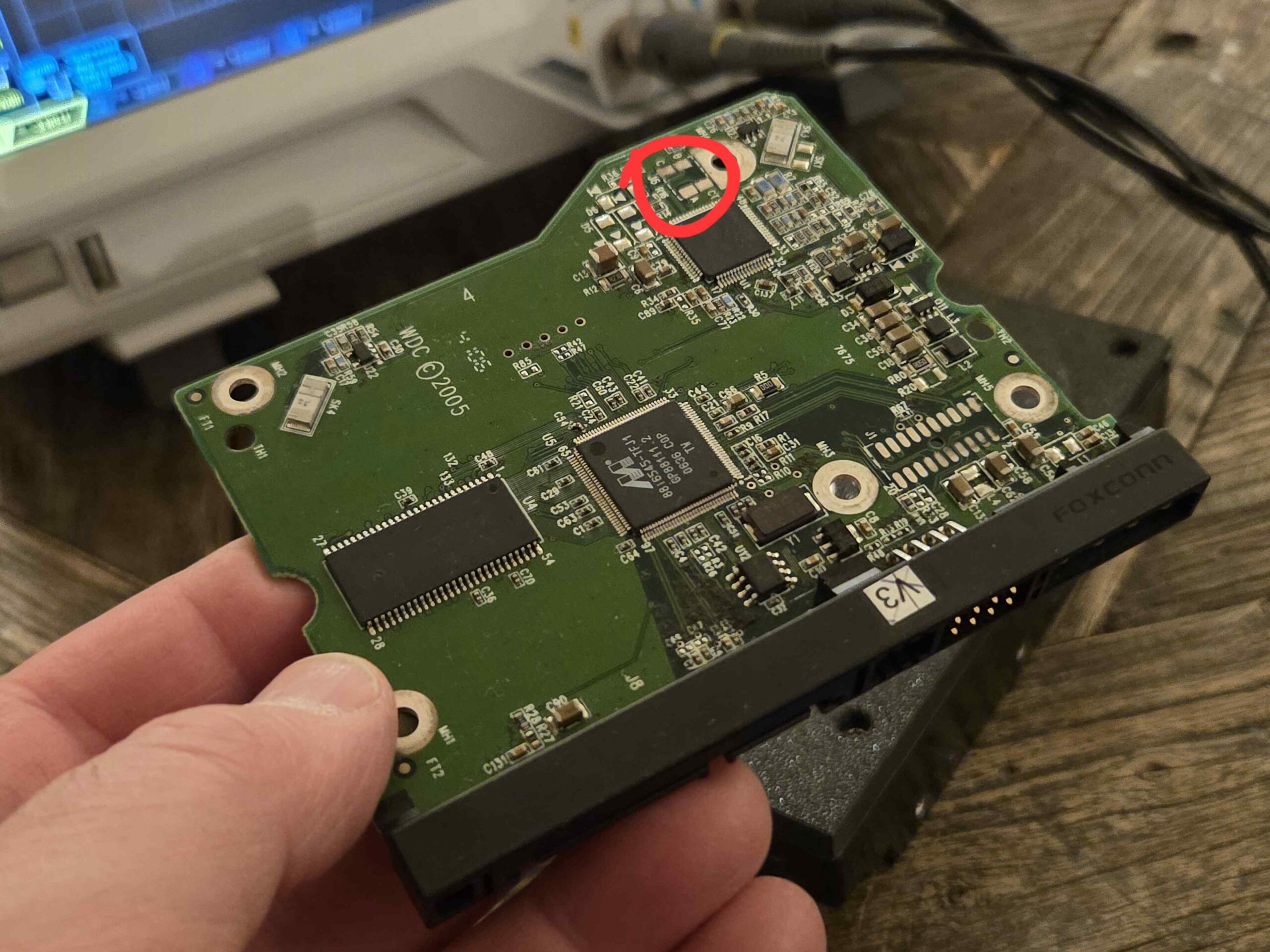
This controller board was no exception. No wires or plugs to disconnect.
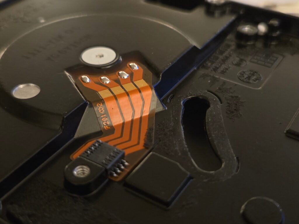
The motor connector is placed under the PCB, so It only needed a set of pogo-style contact pads on the right spot.
I set out to design my own controller board, replicating edge cuts, screw hole positions and motor connector placement.
Using a flatbed scanner to create a image of the controller board, is a great way of getting an accurate representation of the board outline. Edge cuts and screw holes were then drawn using the scan as template. This is a method I’ve previously written about here.
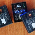
Getting a board
For user interface, I replaced the SATA and power connector rail with a line-up of angled LEDs and pushbuttons. I even added a magnetic pogo connector to simplify flash programming.
I prefer KiCAD for my PCB design jobs. Besides creating the fabrication files, I also make sure to produce an accurate 3D rendering of the board.
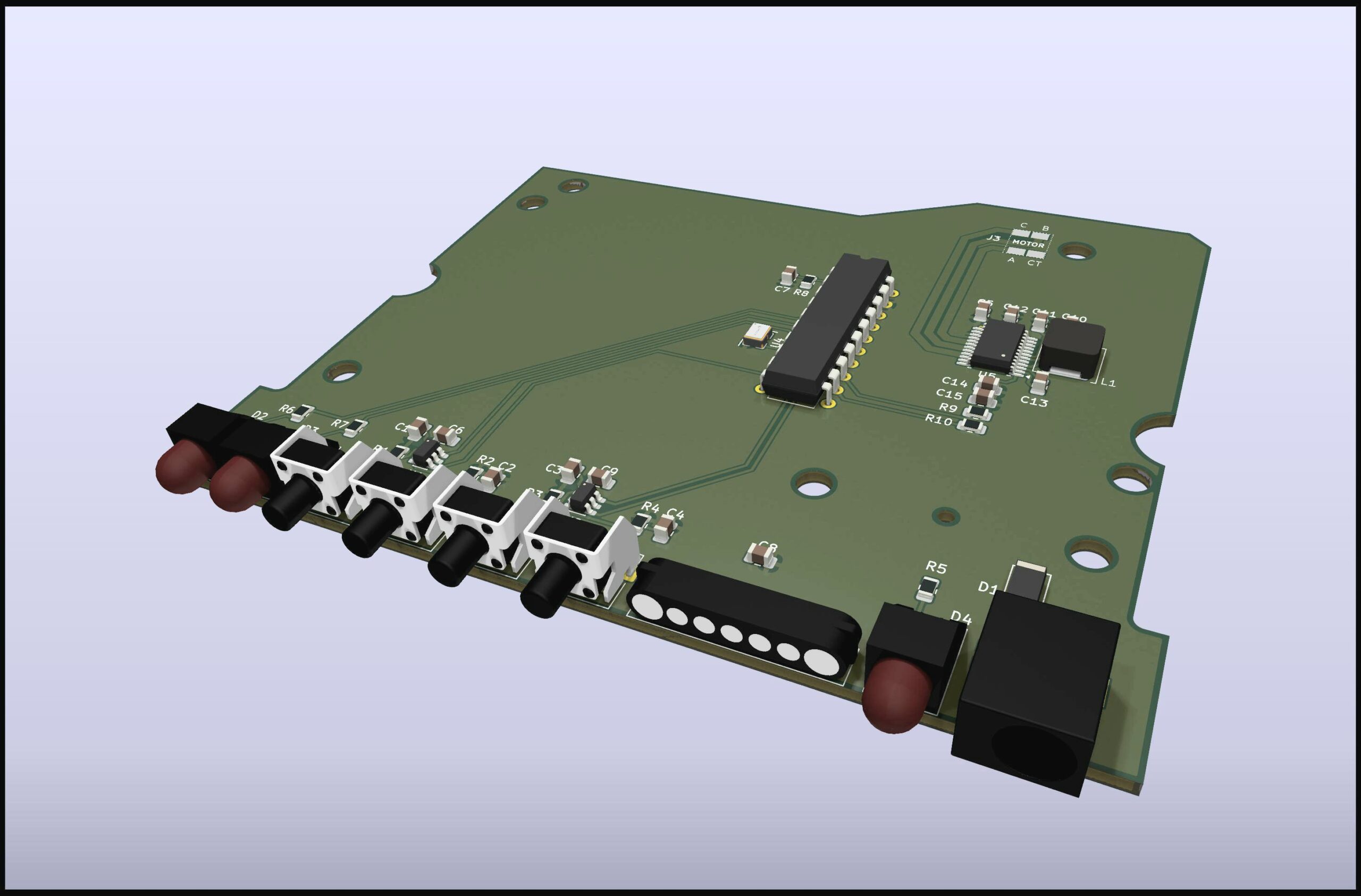
The 3D model is useful when verifying that layout and component heights don’t interfere with the disk’s metal casting.
Printing a dummy PCB in real-size with components in place is well worth the filament, to check if the finished circuit board will actually fit.
The circuit boards for the ringing table arrived from the PCB factory after a couple of days. I went for four layers, giving room for a proper ground plane to reduce EMI.
Both the motor and the power inductor that regulates the voltage for the driver circuit are well known candidates for creating noise. Hence, a solid copper plane tied to ground mitigates some of the problems thay might arise.
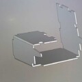
Some 3D work
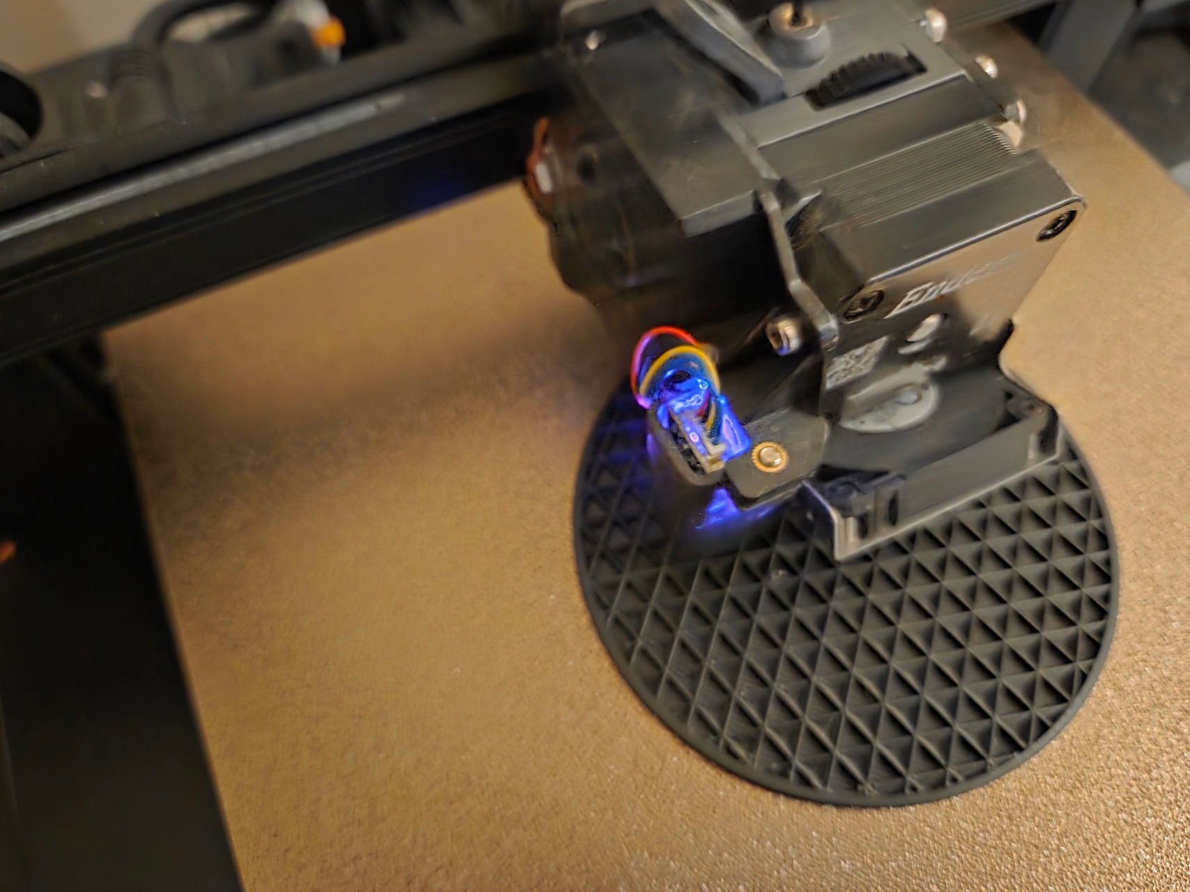
The turntable disc plus the top and side panels for the slide ringer were created in FreeCAD and 3D printed on my Ender 3 S1 Pro printer.
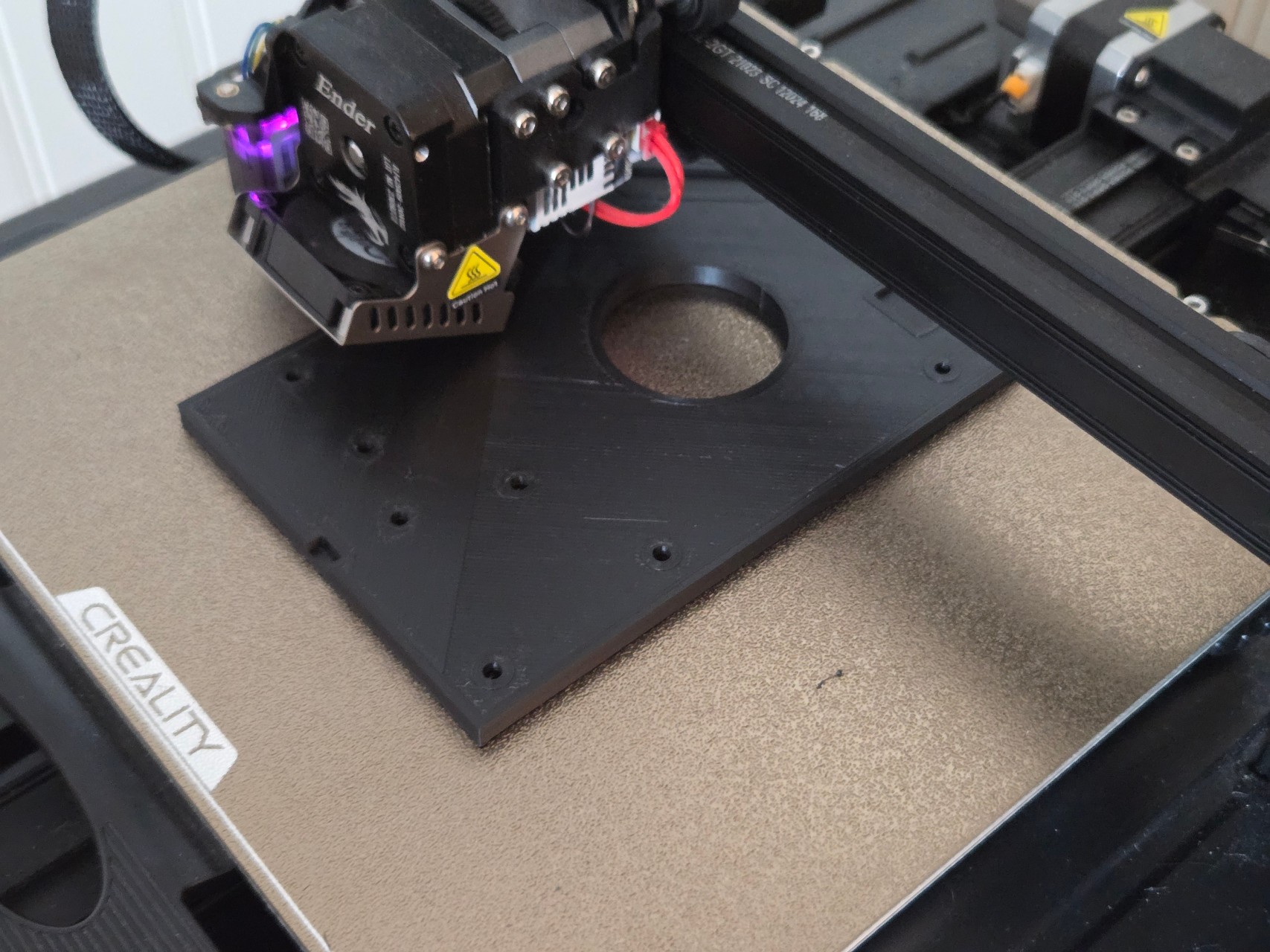
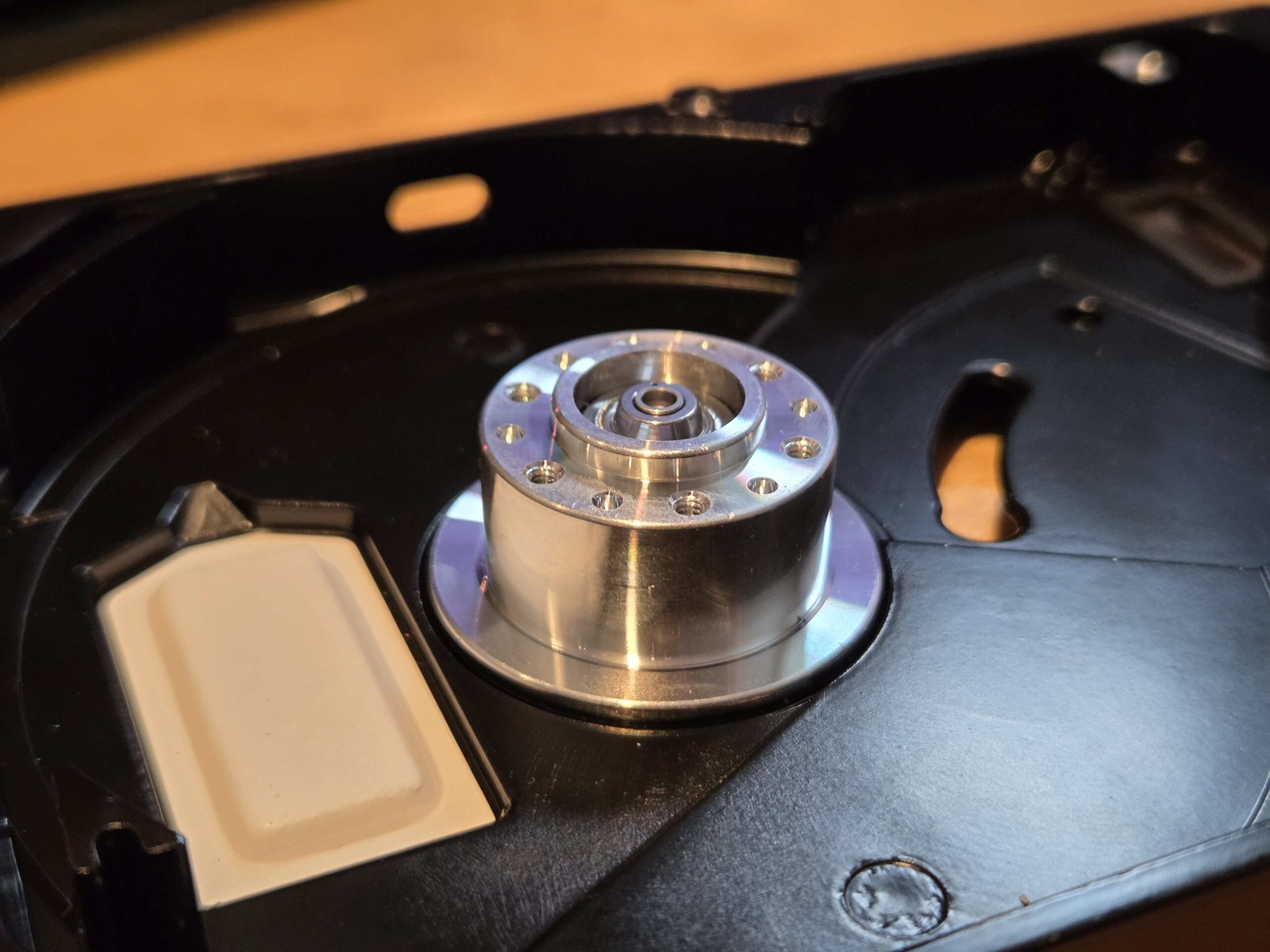
Printing the top panel was a bit of a challenge for this disk, because there were metal part sticking out at various heights beneath the cover. I had to use a scanned image of the open disk to locate the areas where I needed to carve out some millimeters from the cover for it to fit perfectly.
I was a bit uncertain as to whether my printer’s accuracy would be good enough for a stable, non-wobbling ringing table.
Fortunately, it landed well. I printed in PETG for maximim precision, and the prints really worked out just fine.
I added a couple of rubber feet on the bottom, creating enough friction, so that it doesn’t get pushed around when the buttons are pressed.